830-860 SERIES SELF-PROPELLED MOWERS
23
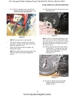
9.
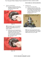
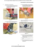
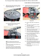
With the wheel, spur gear, idler gear, and drive
pin removed, the dust cover can be lifted off of
the axle. See Figure 6.26.
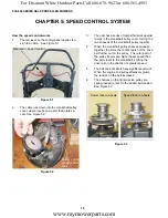
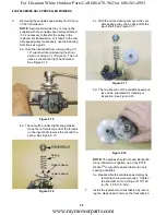
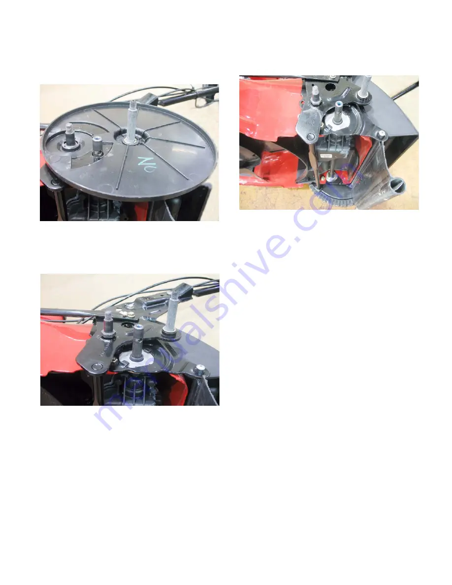
9a. With the dust covers removed, the height
adjuster mechanism is exposed.
See Figure 6.27.
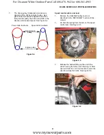
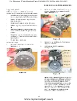
NOTE:
The height adjuster bracket pivots
around the shouldered stud that carries the idler
gear.
•
The idler gear remains at a fixed distance from
the drive axle (spur gear).
•
The wheel axle, attached to the height adjuster
bracket, pivots around the stud, keeping the idler
gear also at a fixed distance from the wheel axle.
Figure 6.26
Figure 6.27
10.
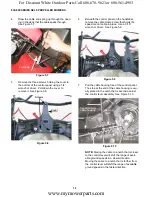
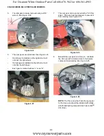
Transmission removal from the 860 Series is
similar to the 830 Series: See Figure 6.28.
10a. Set the cutting height to the highest posi-
tion.
10b. Support the mower, tipped-back, with the
rear wheels elevated.
10c. Remove the baffle as described in Chapter
4: Drive belt and baffles.
10d. Remove the rear wheels, spur gears, drive
pins, idler gears, and dust covers.
10e. Disconnect the height adjustment connec-
tor link from the left rear height adjuster.
10f. Remove the height adjustment handle from
the right rear height adjuster.
10g. Remove both idler bearing studs.
10h. Remove the wheel carrier weldment.
10i. Release the axle bearings.
10j. Loosen the bolts that hold the right rear
height adjuster to the mowing deck.
10k. Slip the transmission assembly to the right
to remove the axle from the left axle bear-
ing, then move it left to free it of the right
axle bearing.
10l. Disconnect the clutch cable, and remove
the transmission.
Figure 6.28
www.mymowerparts.com
For Discount White Outdoor Parts Call 606-678-9623 or 606-561-4983

