830-860 SERIES SELF-PROPELLED MOWERS
4
4.
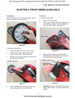
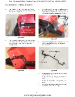
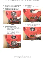
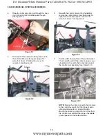
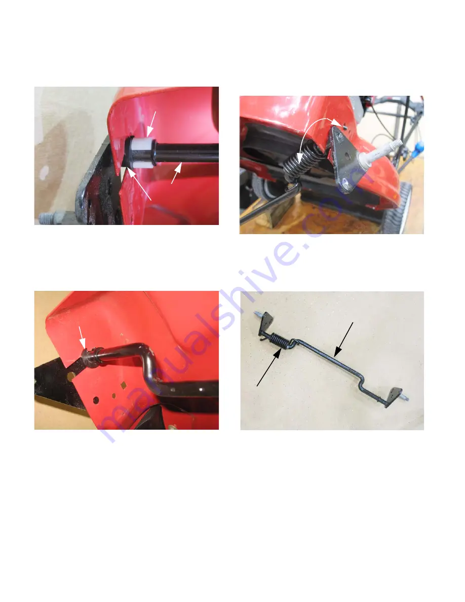
Just inside of the deck shell, near each end of
the axle is a white plastic “C” clip. Remove both
“C” clips. See Figure 2.5.
5.
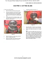
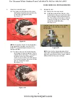
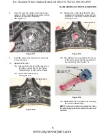
The “C” clips hold flanged hex bushings into key-
hole slots in the deck shell. Slide the hex bush-
ings in to release them from the deck shell.
See Figure 2.6.
6.
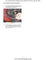
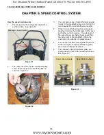
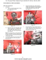
As the flanged hex bushings are released from
the deck shell, the axle will come free of the
shell. Maneuver the front axle to unhook the tor-
sion spring from the deck shell. See Figure 2.7.
7.
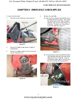
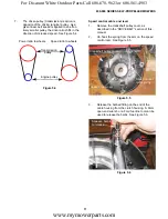
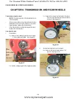
The torsion spring is captive on the front axle. If
either is damaged, both must be replaced.
See Figure 2.8.
8.
Reinstall the front axle by reversing the steps
used to remove it.
•
Replace the “C” clips if they have lost their ten-
sion.
•
Replace the flanged hex bushings if they are
worn.
•
Do not trim the flanged hex bushings to ease
installation. They should be tight.
Figure 2.5
C clip
Front axle
Flanged hex bushing
Figure 2.6
Flanged hex bushing
Figure 2.7
Torsion
spring
Figure 2.8
Front axle weldment
Torsion spring
www.mymowerparts.com
For Discount White Outdoor Parts Call 606-678-9623 or 606-561-4983


