background image

Summary of Contents for AutoDrive 13AU604H402

Page 1: ...ing applicable local or state laws if any If a spark arrester is used it should be maintained in effective working order by the operator In the State of California the above is required by law Section 4442 of the California Public Resources Code Other states may have similar laws Federal laws apply on federal lands A spark arrester for the muffler is available through your nearest engine authorize...

Page 2: ...port department Every tractor has a model plate You can locate it by lifting the seat and looking at the seat bracket An example of what the model plate will look like is shown below This is where your model number will be This is where your serial number will be Copy the moder number here Copy the serial number here _ OHIO 44136 SECTION 3 CALLING CUSTOMER SUPPORT LOCATE YOUR MODEL NUMBER AND SERI...

Page 3: ...an adjustment or repair to protect eyes from foreign objects Stop the blade s when crossing gravel drives walks or roads Be sure the area is clear of other people before mowing Stop machine if anyone enters the area Never carry passengers Disengage blade s before shifting into reverse and backing up Always look down and behind before and while backing Be aware of the mower and attachment discharge...

Page 4: ...ur foot on the ground Do not use grass catcher on steep slopes 3 CHILDREN Tragic accidents can occur if the operator is not alert to the presence of children Children are often attracted to the machine and the mowing activity Never assume that chil dren will remain where you last saw them Keep children out of the mowing area and in watchful care of an adult other than the operator Be alert and tur...

Page 5: ...nor settings or overspeed the engine Excessive engine speeds are dangerous Observe proper disposal laws and regulations Improper disposal of fluids and materials can harm the environment and the ecology Prior to disposal determine the proper method to dispose of waste from your local Environmental Protection Agency Recycling centers are established to properly dispose of materials in an environmen...

Page 6: ...ines with a slope in excess of 15 degrees a rise of approximately 2 1 2 feet every 10 feet A riding mower could overturn and cause serious injury If operating a walk behind mower on such a slope it is extremely difficult to maintain your footing and you could slip resulting in serious injury Operate RIDING mowers up and down slopes never across the face of slopes ...

Page 7: ... cause the engine to smoke This will result in poor engine performance and could cause perma nent engine damage Place the hold down strap in position over the The gasoline tank is located under the hood and has a capacity of approximately two gallons Do not overfill WARNING Gasoline produces noxious battery to secure it in place See Figure 2 Rubber i_ Terminal _ _ Positive Boot P f Negative Hold d...

Page 8: ...ontrol Lever I Parking Brake Button C PTO Power Take Off Knob J Shift Lever D Indicator Monitor Hour Meter K Seat Adjustment Lever E Lift Lever L Cup Holder F Choke Control if so equipped M Cruise Control Button G AutoDrive Pedal NOTE Any reference in this manual to the RIGHT or LEFT side of the tractor is observed from operator s position ...

Page 9: ...it position CHOKE CONTROL On some units moving the throttle lever all the way forward activates the engine s choke control On atl other units the choke control can be found on the left side of the dash panel and is activated by pulling the knob outward Activating the choke control closes the choke plate on the carburetor and aids in starting the engine Refer to STARTING THE ENGINE in the OPERATION...

Page 10: ...actor unattended BRAKE PEDAL The brake pedal is located on the right front side of the tractor above the AutoDrive pedal along the running board The brake pedal can be used for sudden stops or setting the parking brake NOTE The brake pedal must be fully depressed to activate the safety interlock switch when starting the tractor PARKING BRAKE BUTTON To set the parking brake fully depress the brake ...

Page 11: ...prevents the engine from cranking or starting unless the brake pedal is fully depressed and the PTO switch is in the disengaged OFF position The safety interlock system will automatically shut off the engine if the operator leaves the seat before engaging the brake lock The safety interlock system will automatically shut off the engine if the operator leaves the seat with the PTO switch in the eng...

Page 12: ... s carburetor NOTE Do NOT leave the choke control out while operating the tractor Doing so will result in a rich fuel mixture and cause the engine to run poorly STOPPING THE ENGINE Place the PTO switch in the disengaged OFF position Move the throttle control into the SLOW turtle position and allow the engine to idle down for ten seconds Failure to do so may result in an engine afterfire Turn the i...

Page 13: ...othly and carefully to reduce the possibility of flipping the tractor over backward OPERATING THE HEADLIGHTS To turn the tractor s headlights on Start the engine following the instructions earlier in this section Turn the key one notch counterclockwise into the On Lights position of the ignition switch Refer to Figure 4 To turn the tractor s headlights off Turn the key either into the On position ...

Page 14: ...brush and weeds and extremely tall grass Your tractor is designed to mow lawns NOT clear brush Keep the blades sharp and replace the blades when worn Refer to the MAINTENANCE section of this manual for proper blade sharpening instructions SECTION 9 ADJUSTMENTS LEVELING THE DECK _ WARNING Cutting blades are sharp Always protect hands by wearing heavy leather work gloves to grasp blades NOTE Check t...

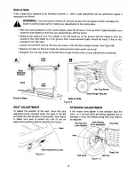
Page 15: ...he hex cap screw on the left deck hanger bracket See Figure 8B Balance the deck so that both blade tip measurements taken earlier are equal Retighten the hex cap screw on the left deck hanger bracket when proper adjustment is achieve_ A Stabilizer Bracket J Deck Jam Nuts i i Hex Cap Screw I Deck Hanger Bracket Front to Rear Side to Side Figure 8 SEAT ADJUSTMENT To adjust the position of the seat m...

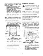
Page 16: ...surement taken behind the axle Adjust if necessary Remove the dowel inserted earlier before attempting to operate the tractor CARBURETOR ADJUSTMENT WARNING If any adjustments are made to the engine while the engine is running e g carburetor disengage all clutches and blades Keep clear of all moving parts Be careful of heated surfaces and muffler NOTE A dirty air cleaner will cause an engine to run...

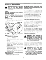
Page 17: ...DECK Any fuel or oil spilled on the machine should be wiped off promptly Do NOT allow grass leaves and dirt to accumulate around the cooling fins of the engine or on any other part of the machine especially the pulleys and other moving parts Clean the underside of the deck with a wisk broom putty knife or forced air after each mowing IMPORTANT Do NOT use a garden hose to clean the cutting deck The...

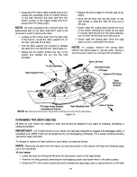
Page 18: ...o properly remount the cutting deck perform the above steps in reverse order Having a second person assist you will ease this procedure Deck Lift Arms PTO Idler Pulley PTO Belt Electric PTO Clutch Deck Stabilizer Bracket Hooks PTO Idler Pulley Bracket Deck Stabilizer Rod mounted on tractor NOTE Beltcoversandother tractorcomponentsnotshownforclarity 42 inchdeck shown Figure 14 Front of Tractor x CH...

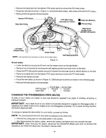
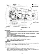
Page 19: ...d belt Route the new belt s as shown in Figure 15 OEM belt part numbers are listed on the following page Remount the belt guards removed earlier PTO Top Belt Bottom Belt 42 Inch Deck 46 Inch Deck 754 0472 754 0476 N A 754 0349 CHANGING THE TRANSMISSION DRIVE BELT S All belts on your tractor are subject to wear and should be replaced if any signs of cracking shredding or rotting are present IMPORTA...

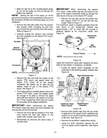
Page 20: ...ulley NOTE Slowly rotate the pulley counterclockwise to roll the belt off of it Remove the upper drive I_eltby pulling it up through the battery tray opening Reroute the new upper drive belt as shown in Figure 16 Lower Drive Belt NOTE Proper removal of the lower drive belt requires the removal of several tractor components Read through the following procedure prior to attempting it to determine if...

Page 21: ...ounds and 50 foot pounds Remove the drive belt by feeding it from both ends toward the front idler pulley on the double idler bracket See Figure 16 Reassemble by following the above steps in reverse order IMPORTANT When remounting the electric PTO clutch make certain that the stud found to the right of the engine crankshaft slides up through the hole found in the top of the electric PTO clutch Hol...

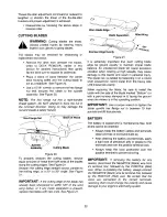
Page 22: ...th new ones See Figure 21 Worn Blade Edge Blade Separation Wind Wing Figure 21 It is extremely important that each cutting blade edge be ground equally to maintain proper blade balance An unbalanced blade will cause excessive vibration when rotating at high speeds may cause damage to the tractor and result in personal injury The blade can be tested by balancing it on a round shaft screwdriver Grin...

Page 23: ...od mounted behind the top of dash panel on the support bar Pull the fuse out and compare it with Figure 22 to determine if it is good or bad GOOD BAD Figure 22 SECTION 11 LUBRICATION d_i WARNING Always stop the engine and disconnect the spark plug wire s and ground against the engine before performing any maintenance ENGINE Lubricate the engine with motor oil as instructed in the separate engine m...

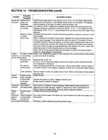
Page 24: ...ce the wire or repair with electrician s tape if the wire strands have not been damaged Note Look for a wire pinched between body panels burned by the exhaust pipe or muffler or rubbed against a moving part Refer to the OPERATION section of this manual for the correct position of the throttle control and choke for starting Gasoline tank empty Fill Fuel line or in line fuel filter plugged Remove an...

Page 25: ...25 ...

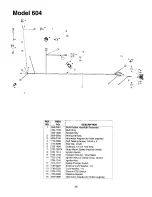
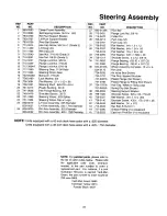
Page 26: ... Bulb Socket Headlight Assembly Bulb Only Socket Only Wiring Harness Alternator Adapter for Intek engines Self Tapping Screw 1 4 20 x 5 Hex Nut 1 4 20 Solenoid 12 volt 100 Amp Snap Mount Safety Interlock Switch Ignition Switch Indicator Monitor Hour Meter Ignition Key w plastic cover shown Ignition Key Safety Plunger Switch External Lock Washer 1 4 Lock Washer 1 4 Electric PTO Switch Retainer Brac...

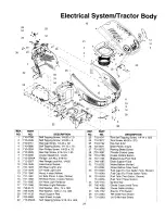
Page 27: ...ellow LH Head Light Reflector RId Head Light Reflector Flat Washer 28 x 74 x 063 Flat Washer 349 x 1 0 x 063 Hood Support Rod Heat Shield 4 style Self Tapping Screw 5 16 18 x 625 REE NO 23 24 25 26 27 28 29 30 31 32 33 34 35 36 37 38 39 I 3 38 4 PART NO 710 1017 710 3217 712 0142 731 0071 731 0072 731 1857 731 2106 747 1155 749 1087 731 2232 731 2234 751 0603 751 0649 75 0659 751 0658 725 1745 746...

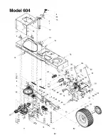
Page 28: ...Model 604 49 45 41 39 _ 46 6 _45 36 47 16 28 35 _32 28 11 50 I I l 51 17 j 22 j 10 j 20 16 28 ...

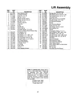
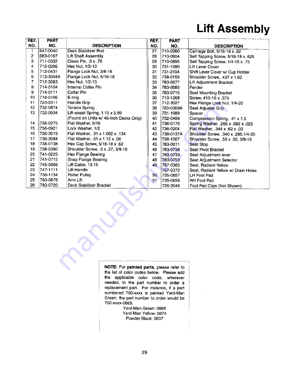
Page 29: ...5 x 27 3 8 16 46 783 0738 Hex Flange Bearing 47 783 0739 Snap Flange Bearing 48 783 0753 LiftCable 16 16 49 757 0365 Lift Handle 757 0372 Roller Pulley 50 735 0657 Arm Lift 51 735 0656 Deck Stabilizer Bracket 726 3046 DESCRIPTION Carriage Bolt 5 16 18 x 62 Self Tapping Screw 5 16 18 x 625 Self Tapping Screw 1 4 15 x 75 Lift Lever Cover Shift Lever Cover w Cup Holder Shoulder Screw 437 x 1 62 Lift ...

Page 30: ...Model 604 24 43 42 23 19 41 2 4 _ 38 21 14 18 44 11 45 3 20 22 13 20 34 7 Q _ _J 9 16 26 L 29 33 31 25 30 ...

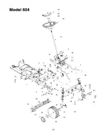
Page 31: ...5 36 37 38 39 4O 41 42 43 44 45 726 0341 736 0162 736 0187 736 0316 1736 0285 738 1011 741 0659 741 0660 634 0105A 634 0172 734 0255 i734 1731 741 0487A 741 0706 734 1787A 727 0425A 783 0653 738 1020 736 0331 738 0140 736 0242 710 0643 737 3000 710 0525 Push Cap 3 4 Flat Washer 64 x 1 0 x 12 Flat Washer 64 x 1 24 x 06 Flat Washer 78 x 1 59 x 06 Flat Washer 635 x 1 589 x 06 Shoulder Screw 5 x 2 2 3...

Page 32: ...7 38 I 30 9 40 _ 8 44 69 J 62 _ 76 12 p_ 15 17 19 49 33 10 23 39_ 14 16 82 J J 83 81 8O 32 ...

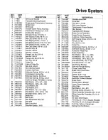
Page 33: ...oulder Screw 625 x 217 Brake Rod Belt Guard Idler Adjustment Rod 3 8 Shift Rod Belt Guard Rod Shoulder Spacer 38 ID REFT I PART NO NO 45 754 0467 46 754 0468 47 756 0981 48 783 0637 49 783 0667 50 783 0669 51 783 0714 52 647 0031 53 647 0032 54 683 0266 55 710 1135 58 711 0736 57 711 1363 58 714 0104 732 0437 732 0955 735 0662 735 3049 736 0140 736 0187 736 0204 738 0155 738 0507B 741 0225 741 306...

Page 34: ...Model 604 5 12 11 13 10 20 40 14 15 38 34 ...

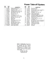
Page 35: ... Tapping Screw 1 4 20 x 5 Flange Lock Nut 7 16 20 Lower Frame Assembly Engine Pulley 3 56 OD 26 714 0118 27 736 0277 28 712 3004A 29 783 0653A 3O _683 0293 683 0197 31 _738 3056 32 717 1708 33 _738 0785 736 0171 3534 710 3157 i 36 1710 3011 37 756 0627 38 754 0472 754 0476 i 39 783 0349 i 40 783 0891 Square Key 1 4 x 1 5 Flat Washer 1 03 x 1 62 x 095 Flange Lock Nut 5 16 18 Steering Support Bracke...

Page 36: ...Model 604 46 inch Deck 10 10 38 33 18 14 16 26 28 35 25 _26 11 41 12 49 17 13 17 42 49 36 ...

Page 37: ... Three n one Bade Star Center 16 28 RER f PART NO NO 31 742 0612 32 747 1116 33 754 O349 34 756 0627 35 783 0139 36 783 0141 37 783 0142 38 783 0747 39 783 0805 40 16606 41 618 0324 1756 1151 42 683 0198 43 710 0604 44 712 0181 45 712 0271 46 712 3006 47 731 2231 48 736 0270 49 742 0616 50 731 1636 51 1731 1643A 52 _712 3087 53 1712 0291 54 i710 0106 55 1710 0578 56 736 0173 57 753 0852 58 753 085...

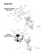
Page 38: ... 604 11 for choke 9 7 _ 13 Briggs Stratton _ 9 Intek Twin _ _P__ _ 22 forthr ttle 14 r _ _ _ _ 21 6 _ _ 10 Kohler 11 forchoke 20 3 Single cylinder _ 26 21 23 2 i 27 21 4 28 14 deflector must face forward 38 ...

Page 39: ...elf Tapping Screw 1 4 20 x 5 Self Tapping Screw 5 16 18 x 625 Screw 10 32 x 625 Socket Cap Screw 5 16 18 x 625 Self Tapping Screw 3 8 16 x 1 25 Hex Nut 3 8 16 Exhaust Gasket Intek Twin Hose Clamp Lock Washer 5 16 Flat Washer 3 8 x 56 x 018 Casing Clamp Fuel Line Hose IMuffler Deflector Muffler Twin Inlet IRH Exhaust Pipe Intek Twin LH Exhaust Pipe Intek Twin iOil Drain Valve i Oil Drain Hose Oil D...

Page 40: ... in your area please check the yellow pages or contact the Customer Support Department of MTD PRODUCTS INC P O Box 368022 Cleveland Ohio 44136 9722 Phone 1 330 220 4683 The return of a complete unit will not be accepted by the factory unless prior written permission has been extended by the Customer Support Department of MTD PRODUCTS INC Transportation charges Transportation charges for the moveme...

Reviews: