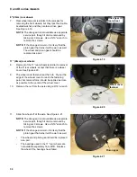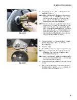
C and D series mowers
20
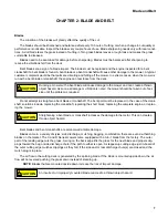
Clutch engagement:
•
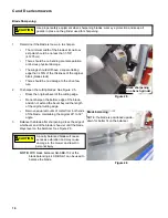
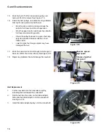
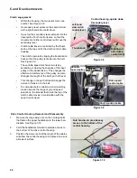
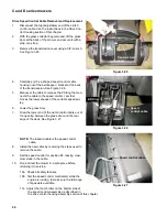
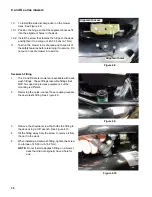
Within the housing, the two levers cross one
another. See Figure 3.8.
•
A secondary lever pivots on the same fulcrum
as the right-hand side control lever.
•
A post on the secondary lever extends into the
travel path of both control levers, so that the
movement of either control lever will move the
secondary lever.
•
Clutch cable travel is controlled by the thumb
knob at the top end of the clutch control cable
housing.
•
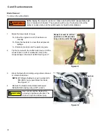
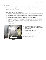
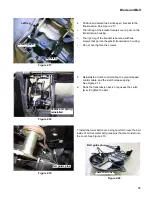
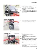
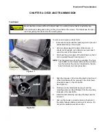
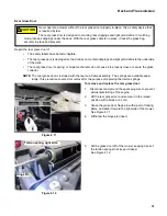
The clutch operates by tipping the transmission
back so that the pulley is drawn into the belt.
See Figure 3.9.
•
The variable speed mechanism works by
spreading or closing the sheaves of the input
pulley on the transmission. This changes the
effective circumference of the pulley, but also
changes the length of the belt’s path of travel.
•
This change in the path of travel changes the
amount of tension on the belt.
•
To compensate for variations in belt clutching
tension across the range of ground speed
selections, the bracket that holds the top of the
clutch cable moves in coordination with the
speed control lever.
Drive Control Housing Removal and Disassembly
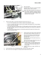
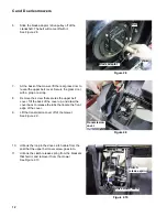
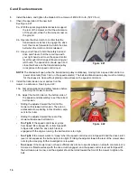
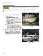
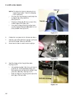
1.
Remove the large wing nuts on the carriage bolts
that fasten the upper handlebars to the lower han-
dlebars. See Figure 3.10.
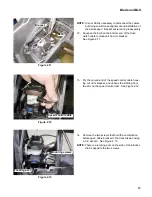
2.
Fold the handlebars forward to provide access to
the bottom of the drive control housing.
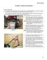
3.
Position the mower so that the length of the cables
will allow the control housing to be placed on a suit-
able work surface.
Figure 3.8
Control housing, upside down
Secondary lever
Left-hand
side clutch
control lever
Right-hand
side clutch
control lever
Thumb knob
Figure 3.9
Clutch control cable
Drive speed
control cable
Variable
speed pulley
Figure 3.10
Fold handles to provide easy
access to the bottom of the
control housing.

