Blade and Belt
21
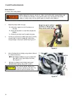
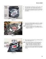
4.
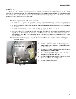
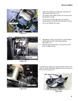
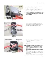
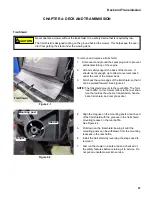
The control housing is held together and fastened to
the upper handlebar by four screws.
5.
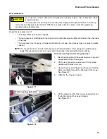
Remove all four screws using a 3/8” wrench. The
shoulder screws go through the handlebar.
See Figure 3.11.
6.
Carefully separate the two halves of the control hous-
ing just enough to allow the housing to be removed
from the handlebar.
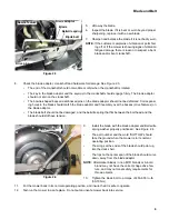
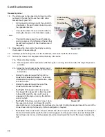
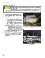
7.
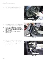
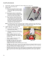
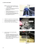
Move the control housing to the workbench, and
carefully separate the bottom half of the housing from
the top half of the housing. See Figure 3.12.
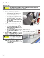
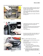
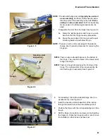
8.
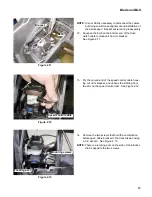
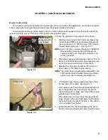
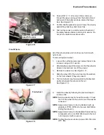
Lift the secondary lever off of the fulcrum post that it
shares with the leftt-hand side control lever.
See Figure 3.13.
9.
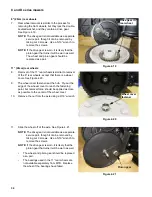
Slip the cable-end barrel out of the hole in the sec-
ondary lever.
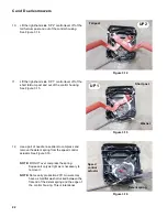
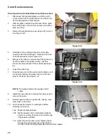
NOTE:
The levers are embossed with indications of their
position and order of assembly into the control
box. The first parts removed would be the last
parts installed.
•
The ribbed side of the secondary lever is embossed
“UP3”.
•
The next visible surface after the secondary lever is
removed is the top of the left hand side control lever,
embossed “UP2”.
•
The right hand side control lever is embossed “UP1”.
Figure 3.11
Shoulder screws
Screws
Figure 3.12
Bottom half of
control housing
Top half of control
housing
Figure 3.13
Secondary lever
Clutch control cable

