Deck and Transmission
47
5.
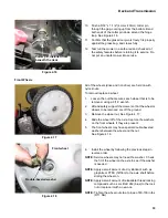
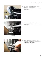
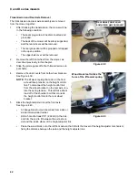
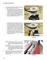
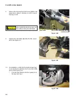
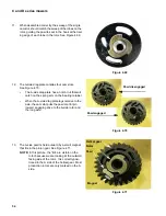
Once the nut is removed, the top sheave will slide off
of the double-D shaped shaft. See Figure 4.52.
6.
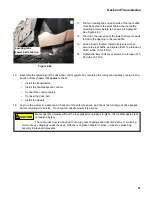
The lower sheave mates to the upper pulley with
splines.
7.
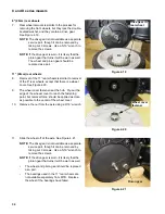
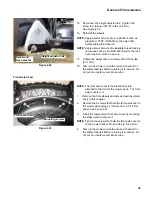
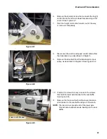
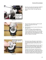
The lower sheave should lift out of the bearing that
supports it on the speed control cam.
See Figure 4.53.
8.
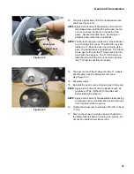
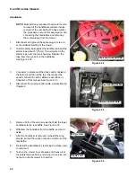
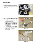
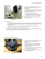
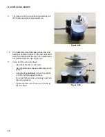
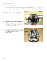
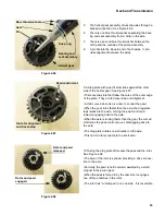
Shims adjust the range of movement of the sheaves.
See Figure 4.54.
•
If there is not an issue with the available speed
range, do not change the size or number of shims.
•
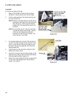
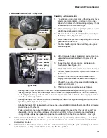
Correct shimming will result in the arm on the speed
control cam being very nearly aligned with the blue
rubber oil plug in the top of the transmission housing
when the sheaves are fully closed.
•
The hole in the arm of the speed control cam will
over-lap about half-way with they recess in the top of
the blue rubber plug when the sheaves are fully
closed.
•
If there is not enough shimming, the mower may not
have the full low-end of the speed range, and the
speed control cam may over-rotate, getting jammed
against the back edge of the ramp that raises it.
•
If there are too many shims, the sheaves will not
spread far enough apart. The mower will lose the top
end of the drive speed range, and the operator may
over-stress the speed control cable in trying to move
the speed control selector to the 4th speed detent.
Figure 4.52
Upper sheave:
drives input shaft
with double-D
drives lower
sheave with spline
Figure 4.53
Speed control cam
Figure 4.54
Shims between the bearing
and the pulley adjust the
speed range.

