Deck and Transmission
53
5.
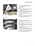
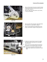
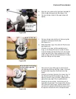
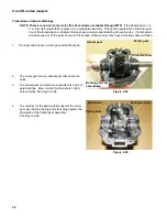
The helical gear assembly drives the axles through a
splined connection. See Figure 4.66.
6.
There is one blue thrust washer separating the bear-
ing and seal assembly from a cirlip on the axle.
7.
There is a second blue thrust washer between the
circlip and the outside of the pinion assembly.
8.
A pin fits into the inboard end of both axles. It pro-
vides alignment between the axles.
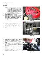
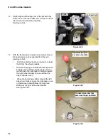
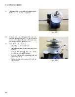
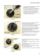
9.A drag plate with a set of slots rides against the other
side of the helical gear: See Figure 4.67.
•There are two slots that follow the curve of the outer edge
of the plate. They are for travel stop and alignment.
•A third curved slot acts as a cam to control the pawl.
•When the gear turns faster than the axle, the drag plate
lags relative to the axle, moving the pawl control pin
inward, engaging drive to the axle.
•When the axle is turning faster than the gear, the curved
slot forces the pawl control pin out, disengaging drive to
the axle.
•The drag plate rotates on a shoulder on the axle.
•This non-A rotor connects to the short axle.
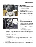
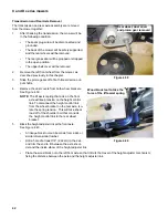
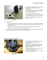
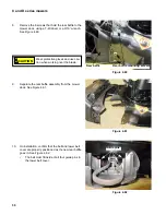
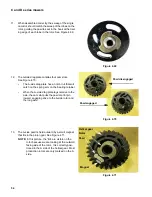
10.Taking the drag plate off reveals the pawl and the rotor.
See Figure 4.68.
•The bore of the rotor is splined, providing a drive connec-
tion to the axle.
•Normally, the pawl is held outward, assisted by a small
magnet in the pinion gear.
•When the pawl is forced in by the cam slot, it engages
one of three notches in the rotor.
•The rotor has “A” stamped in on one side. It is reversible.
Figure 4.66
Blue thrust washers
Axle
Pin
Snap ring
Bearing and
seal assembly
Helical gear
Figure 4.67
Slots for alignment
and travel-stop
Pawl control slot
Figure 4.68
Rotor and pawl
released
Rotor and pawl
engaged

