Auger Housing Components
37
Rebuilding the joy stick
To rebuild the joy stick:
1.
Remove the joy stick by following the steps described
in the joy stick section of this chapter.
2.
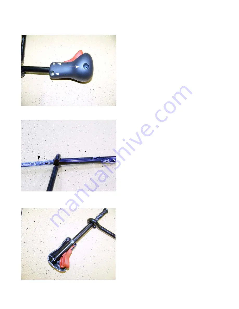
Remove the three screws (indicated by the arrows)
that hold the knob together using a #2 phillips screw-
driver. See Figure 4.28.
3.
Carefully remove one of the knob halves.
NOTE:
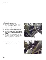
The actuator pin is under spring load, held in place
by the trigger. When the actuator pin is fully
extended the tension is minimal.
4.
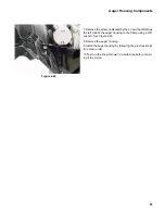
Remove the trigger, catching the actuator pin and
spring as they come out of the joy stick tube.
5.
Remove the remaining knob half.
6.
Clean and inspect all of the parts.
NOTE:
If there are any sign of wear or damage to the trig-
ger, it must be replaced.
7.
Apply a small amount of white lithium grease to the
pockets of the knob, where the trigger rotates.
8.
Apply a small amount of white lithium grease to the
blade of the trigger that engages the actuator pin.
9.
Install the spring on the actuator pin
10.
Lightly coat the upper half of the actuator pin with
white lithium grease.
11.
Insert the actuator pin into the joy stick tube so that
the groove in it lines up with the slot in the joy stick
tube.
12.
Install one of the knob halves on to the joy stick tube.
13.
Install the trigger so that the blade is resting in the
groove of the actuator pin.
14.
Install the remaining knob half and tighten the screws
to a torque of 13 - 15 in lbs (1.5 - 1.7 Nm).
15.
Test the joy stick by following the procedures
described in the joy stick testing section of this chap-
ter.
16.
Install the joy stick by following the procedures
described in the joy stick section of this chapter.
17.
Test run the snow thrower in a safe area before
returning it to service.
Figure 4.28
Figure 4.29
Actuator pin
Figure 4.30
Summary of Contents for Cub Cadet 221 HP
Page 2: ......
Page 4: ...II ...
Page 48: ...221 HP LHP 44 ...
Page 49: ......
Page 50: ...MTD Products Inc Product Training and Education Department FORM NUMBER 769 06633 04 2011 ...


