background image

 15

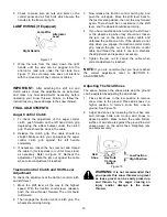
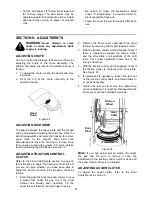
ADJUSTING SHIFT ROD

1.

Remove the hairpin clip and flat washer from the
ferrule and remove the ferrule from the shift
lever. Place the shift lever in the fastest forward
speed position.

Models 602, 642, 662:

2.

Push up on the shift arm assembly as far as it
will go. Thread the ferrule up or down the shift
rod and align with the lower hole on the wider
side of the shift lever assembly behind the
handle panel. Secure the ferrule to the shift arm
assembly again with the hardware earlier
removed.

Models 614, 644, 664, and 6A4:

3.

Push down on the shift arm assembly as far as it
will go. Thread the ferrule up or down the shift
rod and align it with the hole closest to the shift
knob on the narrow side of the shift lever
assembly behind the handle panel.

NOTE: 

Make certain to check for correct

adjustment of the shift rod as instructed in the Final
Adjustments section before operating the snow
thrower.

CARBURETOR ADJUSTMENT

WARNING: 

If any adjustments are

made to the engine while the engine is
running (e.g. carburetor), keep clear of
all moving parts. Be careful of heated
surfaces and muffler.

Minor carburetor adjustment may be required to
compensate for differences in fuel, temperature,
altitude and load.
Refer to the separate engine manual packed with
your unit for carburetor adjustment information.

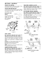
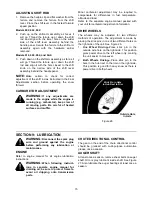
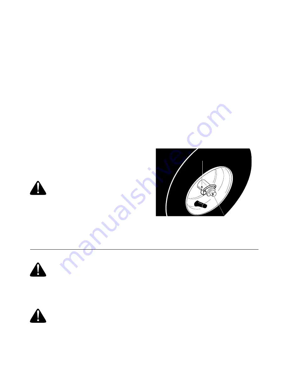
DRIVE WHEELS

The wheels may be adjusted for two different
methods of operation. The adjustment is made by
placing the klick pins in one of two different holes on
the right side of the unit. See Figure 26.

1.

One Wheel Driving—Place klick pin in the
outside axle hole on the right side. This position
gives power drive to the left wheel only, making
the unit easier to maneuver.

2.

Both Wheels Driving—Place klick pin in the
hole in the hub next to the rim on the right side.
This position is good for heavy snow as there is
power drive in both wheels.

Figure 26  

SECTION 9:  LUBRICATION

WARNING: 

Disconnect the spark plug

wire and ground against the engine
before performing any lubrication or
maintenance.

ENGINE

Refer to engine manual for all engine lubrication
instructions.

WARNING: 

When following instruct-

ions in separate engine manual for
draining oil, be sure to protect frame to
avoid oil dripping onto transmission
parts.

CHUTE DIRECTIONAL CONTROL

The gear on the end of the chute directional control
should be greased with multi-purpose automotive
grease once a season.

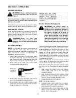
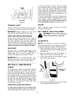
AUGER SHAFT

At least once a season, remove shear bolts on auger
shaft. Oil or spray lubricant inside shaft. See Figure
27. Also lubricate the auger bearings at least once a
season.

Klick Pin in Hole

in Hub Next to Rim

Outside Hole

in Axle

Summary of Contents for E644F

Page 1: ...ith a spark arrester meeting applicable local or state laws if any If a spark arrester is used it should be maintained in effective working order by the operator In the State of California the above is required by law Section 4442 of the California Public Resources Code Other states may have similar laws Federal laws apply on federal lands A spark arrester for the muffler is available through your...

Page 2: ...TION 2 CALLING CUSTOMER SUPPORT LOCATE YOUR MODEL NUMBER AND SERIAL NUMBER Record this information in the space provided To find your unit s specific model number and serial number see SECTION 1 FINDING YOUR MODEL NUMBER If you are having difficulty assembling this product or if you have any questions regarding the controls operation or maintenance of this unit please call the Customer Support Dep...

Page 3: ...rating in reverse 2 PREPARATION Thoroughly inspect the area where the equipment is to be used and remove all door mats sleds boards wires and other foreign objects Disengage all clutches and shift into neutral before starting engine Do not operate equipment without wearing adequate winter outer garments Do not wear jewelry long scarfs or other loose clothing which could become entangled in moving ...

Page 4: ...e power to collector impeller when transporting or not in use Use only attachments and accessories approved by the manufacturer of snow thrower such as wheel weights counter weights cabs etc Never operate the snow thrower without good visibility or light Always be sure of your footing and keep a firm hold on the handles Walk never run Muffler and engine become hot and can cause a burn Do not touch...

Page 5: ... snow thrower is designed so that the bolts may shear Two replacement shear bolts and nuts are provided for your convenience Store in a safe place until needed E ATTACHING THE CLUTCH GRIPS Flat Washers 5 16 I D x 5 8 O D 736 0264 Hex Bolts 5 16 18 x 1 3 4 Long 710 3180 Hex Bolts 5 16 18 x 3 4 Long 710 3008 Hex Nuts 5 16 18 Thread 712 3010 Saddle 784 5599 Lock Washers 5 16 I D 736 0119 Carriage Bol...

Page 6: ...plete the assembly Follow assembly instructions in this operator s manual to make the job safe and easy You will need the following tools to assemble the snow thrower Attaching the Handle Assembly Hardware A and E Lay loose parts out on flat surface Figure 3 1 Attach left handle and left grip bracket to handle panel with two carriage bolts lock washers and hex nuts Be sure the bend in the grip bra...

Page 7: ... 7 9 Hold the handle assembly up to the bottom of the snow thrower frame and thread the hex bolt into the lower hole in snow thrower frame Do not tighten at this time See Figure 8 Figure 8 10 Repeat process on the other side 11 Raise the handle assembly into the upright position and align the top holes in the handles with the top holes in the snow thrower frame Attach using hex bolts 1 3 4 Long lo...

Page 8: ...gure 11 4 Secure the ferrule to the shift arm assembly with flat washer and hairpin clip NOTE Make certain to check for correct adjustment of the shift rod as instructed in the FINAL ADJUSTMENTS section before operating the snow thrower ATTACHING CLUTCH CABLES Hardware D 1 Thread the hex jam nuts all the way up the threaded portion of the Z ends 2 Make certain all cables are in the grooves of the ...

Page 9: ...the hole in the plastic bushing in the chute bracket See Figure 15 Place the second flat washer on the chute directional control and secure with hairpin clip Figure 15 3 Thread one hex nut onto the eyebolt on the chute directional control assembly until there is at least two inches of threads showing between the nut and the head of the eyebolt See Figure 16 Figure 16 4 Place the eyebolt into the h...

Page 10: ... Then engage the traction control clutch grip The wheels should stop turning 3 Now release the traction control clutch grip and push the unit again Move the shift lever back to the fast reverse position then all the way forward again There should be no resistance in the shift lever and the wheels should keep turning 4 If you have resistance when moving the shift lever or the wheels stop when they ...

Page 11: ... Model 602 642 and 662 See Figure 22 for Models 614 644 664 and 6A4 The auger control clutch is located on the left handle Squeeze the auger control clutch against the handle to engage the augers Release to stop the snow throwing action TRACTION CONTROL CLUTCH See Figure 21 for Model 602 642 and 662 See Figure 22 for Models 614 644 664 and 6A4 The traction control clutch is located on the right ha...

Page 12: ...ate on 120 volt AC household current It must be properly grounded at all times to avoid the possibility of electric shock which may be injurious to the operator Follow all instructions carefully If the house wiring system is not a three wire grounded system do not use this electric starter under any conditions Follow all instructions carefully Determine that your house wiring is a three wire groun...

Page 13: ...ing push starter button and spin the starter for several seconds The unusual sound made by spinning the starter will not harm engine or starter Disconnect the power cord from receptacle first and then from switch box Recoil Starter With engine running pull starter rope with a rapid continuous full arm stroke three or four times Pulling the starter rope will produce a loud clattering sound which is...

Page 14: ...ection on page 10 for instructions to adjust the traction control clutch If you are not sure whether you have been able to adjust the traction control clutch properly check as follows 1 Drain the gasoline from the snow thrower or put a plastic film under the gas cap if the snow thrower has already been operated Tip the snow thrower forward onto the auger housing 2 Remove the frame cover underneath...

Page 15: ...d Refer to the separate engine manual packed with your unit for carburetor adjustment information DRIVE WHEELS The wheels may be adjusted for two different methods of operation The adjustment is made by placing the klick pins in one of two different holes on the right side of the unit See Figure 26 1 One Wheel Driving Place klick pin in the outside axle hole on the right side This position gives p...

Page 16: ...and 712 0429 hex insert lock nut 5 16 18 thread SHAVE PLATE AND SKID SHOES The shave plate and skid shoes on the bottom of the snow thrower are subject to wear They should be checked periodically and replaced when necessary To remove skid shoes remove the four carriage bolts belleville washers and hex nuts which attach them to the snow thrower Reassemble new skid shoes with the four carriage bolts...

Page 17: ...l and friction wheel disc See Figure 31 Remove and replace belt Reassemble following the instructions in reverse order NOTE The support bracket must rest on the stop bolt after the new belt has been assembled See Figure 31 Figure 30 Figure 31 CHANGING THE FRICTION WHEEL RUBBER The rubber on the friction wheel is subject to wear and should be checked after 25 hours of operation and periodically the...

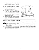
Page 18: ...eel assembly up onto the pin of the shift rod assembly and slide the shaft through the assembly Reassemble in reverse order Figure 32 SECTION 11 OFF SEASON STORAGE WARNING Never store engine with fuel in tank indoors or in poorly ventilated areas where fuel fumes may reach an open flame spark or pilot light as on a furnace water heater clothes dryer or other gas appliance 1 If unit is to be stored...

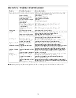
Page 19: ...tor adjusted by an authorized service dealer Loss of power Spark plug wire loose Gas cap vent hole plugged Exhaust port plugged Connect and tighten spark plug wire Remove ice and snow from cap Be certain vent hole is clear Clean see Maintenance section of engine manual Engine overheats Carburetor not adjusted properly Refer to the engine manual packed with your unit or have carburetor adjusted by ...

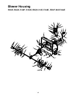
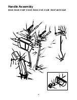
Page 20: ...02E E642E E642F E662E E662H 614E E644E E664F AND E6A4E 1 2 3 4 5 6 7 8 9 10 11 12 13 9 8 14 15 16 17 7 18 18 7 19 20 21 16 6 22 23 13 13 6 7 24 6 16 26 27 28 25 29 30 31 32 33 34 36 37 33 32 32 33 35 37 36 33 32 31 30 6 38 ...

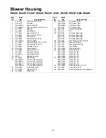
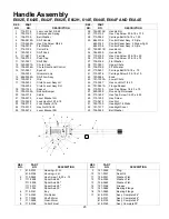
Page 21: ...ly 684 0055B 30 Housing Assembly 22 736 0169 Lock Washer 3 8 23 712 0798 Hex Nut 3 8 16 24 784 5580 Slide Shoe 25 784 5581A 24 Shave Plate 784 5579A 26 Shave Plate 784 5582A 28 Shave Plate 784 5575 30 Shave Plate 26 684 0065 Impeller Assembly 27 715 0114 Pin 28 618 0120 24 Gear Assembly 618 0121 26 Gear Assembly 618 0122 28 Gear Assembly 618 0160 30 Gear Assembly 29 710 0604 Hex Washer Screw 5 16 ...

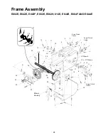
Page 22: ...2E E642F E662E E662H 614E E644E E664F AND E6A4E 1 2 3 4 5 6 7 8 9 11 15 6 7 16 16 17 18 18 19 19 20 20 21 22 23 24 25 26 27 28 29 30 24 53 23 34 35 23 36 38 22 39 40 41 39 42 43 44 45 46 17 47 29 48 49 50 51 52 14 13 7 37 10 12 24 ...

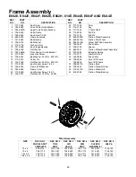
Page 23: ...Hex Cap Screw 5 16 18 x 75 37 736 0185 Flat Washer 38 731 0921 Upper Chute 39 736 0159 5 16 Washer 40 710 0451 Carriage Bolt 5 16 18 x 75 41 710 0276 Carriage Screw 5 16 18 x 1 0 42 720 0284 Knob 43 731 1300A Lower Chute 44 712 3027 Hex Lock Nut 1 4 20 45 731 0851A Flange Keeper 46 710 3015 Hex Cap Screw 1 4 20 x 75 47 629 0058 Round Light Harness 48 710 1652 Hex Tap Screw 1 4 20 x 625 49 710 1003...

Page 24: ...4F AND E6A4E 1 1 2 3 4 4 5 5 6 16 Wheels 13 or 15 Wheels 4 7 7 8 9 10 10 11 11 12 1 5 13 14 15 16 17 18 1 19 20 21 22 23 24 25 25 26 28 29 26 1 1 30 31 32 33 34 8 35 Drive Clutch Cable Auger Clutch Cable Auger Clutch Cable Blower Housing 36 20 20 37 37 38 39 40 27 ...

Page 25: ...14 0143 Klik Pin 27 684 0042B Friction Wheel Assembly 28 656 0012A Friction Disc Wheel 29 684 0013B Wheel Shift Rod Assembly 30 746 0897 Drive Cable 31 748 0190 Spacer 32 684 0021 Friction Wheel Bracket Assembly 33 732 0264 Extension Spring 34 712 0711 Jam Nut 3 8 24 35 746 0898 Drive Cable 36 738 0869 Axle 13 Wheels 738 0830 Axle 16 Wheels 37 784 5617A Friction Plate 38 735 0243 Friction Wheel Ru...

Page 26: ...ew 1 4 28 x 50 13 756 0313 Flat Idler 14 710 1245 Lock Cap Screw 5 16 24 15 712 0181 Lock Jam Nut 3 8 16 16 756 0569 Pulley Half 17 736 0242 Bell Washer 18 736 0505 Flat Washer 19 736 0507 Washer 20 754 0430A Belt 21 756 0967 Auger Pulley 22 736 0247 Flat Washer 23 736 0331 Bell Washer 24 710 0696 Hex Cap Screw 3 8 24 25 748 0360 Pulley 26 710 0654A Hex Washer Screw 3 8 16 x 1 0 27 629 0071 Extens...

Page 27: ... 710 0230 Hex Cap Screw 13 756 0313 Flat Idler 14 712 0181 Lock Jam Nut 3 8 16 15 710 0654A Hex Washer Screw 3 8 16 x 1 0 16 710 1245 Hex Lock Screw 5 16 24 x 875 17 736 0242 Bell Washer 340 ID x 872 OD 18 736 0505 Flat Washer 341 ID x 50 OD 19 756 0967 Pulley Auger 20 756 0569 Pulley Half 21 754 0430A V Belt 22 736 0247 Flat Washer 23 736 0331 Bell Washer 39 ID x 1 13 OD 24 710 0696 Hex Cap Screw...

Page 28: ...eparate manufacturer s warranty Please refer to the applicable manufacturer s warranty on these items b Routine maintenance items such as lubricants filters blade sharpening and tune ups or adjustments such as brake adjustments clutch adjustments or deck adjustments and normal deterioration of the exterior finish due to use or exposure c Log splitter pumps valves and cylinders have a sepa rate one...

Reviews: