background image

4

SECTION 2:  ASSEMBLY & OPERATION

NOTE:


References to LEFT, RIGHT, FRONT and 

REAR of the tractor are from the operator’s position. 

Before

 assembly, place the tractor on a firm, level 

surface, disengage the PTO, stop the tractor 
engine and set the parking brake.

Assembling Support Brackets

Tractor Model Series 660 through 690 

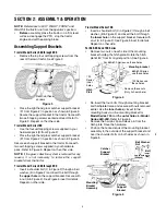
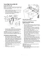
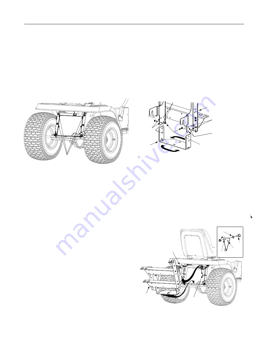
Remove the top four self-tapping screws from the 
rear of the lawn tractor. See Figure 3. 

Figure 3

Place the right hand grass catcher support bracket 
(F1 from Figure 2) in position as shown in Figure 5. 

Secure the support bracket to the tractor frame with 
two self-tapping screws earlier removed. Refer to 
Figure 3. Repeat on the other side.

Tractor Model Series700

Use the four self-tapping screws supplied in your 
hardware pack (D from Figure 2).

Place the right hand grass catcher support bracket 
(F1 from Figure 2) in position as shown in Figure 5. 

Secure each support bracket to the tractor frame with 
two self-tapping screws supplied in your hardware 
pack. Refer to Figure 5. Repeat on the other side.

NOTE:

 If the grass collection system is removed for any

reason, it is not necessary to remove the support
brackets from the tractor.

Tractor Model Series 660 through 690

Insert a shoulder bolt (C in Figure 2) through a bell 
washer, (B in Figure 2) and insert the bolt through 
the 

upper hole

 on the support bracket. Secure with


a nut (A in Figure 2). See Figure 5 inset for details. 
Repeat on other side.

Tractor Model Series700

Insert a shoulder bolt (C in Figure 2) through a bell 
washer, (B in Figure 2) and insert the bolt through 
the 

lower hole

 on the support bracket. Secure with


a nut (A in Figure 2). See Figure 5 inset for details. 
Repeat on other side.

For 660-690 and 700 Series

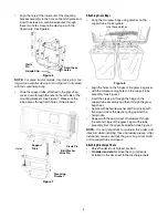
Remove two nuts on each side of the mounting 
bracket holding the hitch plate. Rotate the hitch 
plate 180° from its original position. See Figure 4.

Figure 4

Re-insert the four bolts through mounting bracket 
and hitchplate frame and secure with nuts removed 
earlier. Use the 

inner holes


(closest to the 

mounting hooks) on the mounting bracket 

for 

Model Series 700

 and the 

outer holes

 for 

Model 

Series 660-690.

 Refer to Figure 4.

Remove the hairpin clip and clevis pin from the 
hitch plate. Save the hardware.

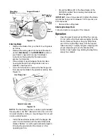
Position the hooked ends of the mounting bracket 
assembly to the outside of the support bracket and 
over the shoulder bolts on both sides as shown in 
Figure 5.

Figure 5

Remove these

screws

Remove these nuts

(Only 2 shown here)

Plate

Hitch 

660-690 Series
use these holes

700 Series use
these holes

For 660-690 Series use these holes

700
Series

Mounting bracket

inner
holes

Catcher 

Bracket

Support

Catcher 

Bracket

Support

Mounting 
Bracket
Assembly

Nut

Bolt

Bell Washer

(660-690)

lower

(700)

hole

upper hole

Summary of Contents for OEM-190-180

Page 1: ... applicable local or state laws if any If a spark arrester is used it should be maintained in effective working order by the operator In the State of California the above is required by law Section 4442 of the California Public Resources Code Other states may have similar laws Federal laws apply on federal lands A spark arrester for the muffler is available through your nearest engine authorized s...

Page 2: ...ion or maintenance of this unit please call the Customer Support Department Call 1 330 220 4MTD 4683 or 1 800 800 7310 to reach a Customer Support representative Please have your unit s model number and serial number ready when you call See previous section to locate this information You will be asked to enter the serial number in order to process your call YOUR RESPONSIBILITY Restrict the use of ...

Page 3: ...item has been identified in Figure 2 for ease of assembly and the letter code assigned here is maintained in assembly instructions However the hardware pack contains more than one of some items Chute Tube Discharge Chute Assembly Bag Assemblies Grass catcher Cover Mounting Support Tube attached to cover Assembly Bracket A B C E F F1 F2 G H For all Model Series 800 tractors only For older Model Ser...

Page 4: ...B in Figure 2 and insert the bolt through the upper hole on the support bracket Secure with a nut A in Figure 2 See Figure 5 inset for details Repeat on other side Tractor Model Series700 Insert a shoulder bolt C in Figure 2 through a bell washer B in Figure 2 and insert the bolt through the lower hole on the support bracket Secure with a nut A in Figure 2 See Figure 5 inset for details Repeat on ...

Page 5: ... cover with the corresponding holes on the support tube assembly See Figure 7 Insert the clevis pin through the hinge on the support tube assembly and then through the grass bag cover Secure with belleville washer and hairpin clip with the crown side of the washer going against the hairpin clip Repeat with the second set of hardware through the second hinge of the grass bag and the tube assembly f...

Page 6: ...p depending on the location of the grass catcher pin on the deck Remove the retainer strap from position B on the discharge chute to position A or C corresponding to the position of the grass catcher pin at A B or C on the deck See Figure 10 Figure 10 Lower the deck to its lowest position Lock the discharge chute in position by hooking the retainer strap over the grass catcher pin on the deck See ...

Page 7: ...tion Attach the grass bags using the slots shown in Figure 14 Close the grass catcher cover Figure 14 Attaching the Discharge Chute Follow instructions on page 5 of this manual Model Series 800 Tractors Model 190 182 only Take out the applicable pair of support bracket F2 in Figure 2 and four self tapping screws F in Figure 2 from the hardware pack Insert shoulder bolt C in Figure 2 through a bell...

Page 8: ...re to install the blade with the side of the blade marked Bottom or with a part number stamped in it facing the ground when the mower is in the operating position Mount the SMALLER of the three blades to the CENTER spindle The remaining two blades are interchangeable IMPORTANT Use a torque wrench to tighten the blade spindle hex flange nut to between 70 foot pounds and 90 foot pounds Remount the c...

Page 9: ...9 NOTES ...

Page 10: ...10 10 19 15 9 13 21 13 4 27 22 11 22 20 26 11 9 13 25 6 6 23 24 31 13 29 7 14 30 13 2 5 1 12 12 18 32 3 SECTION 3 PARTS LIST 36 35 33 37 800 Series 22 20 26 11 25 38 660 690 Series 700 Series ...

Page 11: ...6 731 04153 Discharge Chute 38 42 Bag 18 731 0926B Catcher Tube 731 0899E Chute Tube model 190 180 19 736 0331 Bell Washer 20 736 0407 Bell Washer 21 736 3092 Flat Washer 22 738 1020 Shoulder Screw 23 742 0644 Blade 16 28 Lg model 190 182 24 742 0645 Blade 14 88 Lg model 190 182 25 783 04132A Supt Bracket model 190 180 LH 26 783 04137A Supt Bracket model 190 180 RH 27 783 04138 Support Bracket mod...

Page 12: ...normal deterioration of the exterior finish due to use or exposure d MTD LLC does not extend any warranty for products sold or exported outside of the United States its possessions and territories except those sold through MTD LLC s authorized channels of export distribution e Parts that are not genuine MTD parts are not covered by this warranty f Service completed by someone other than an authori...

Reviews: