background image

 13

SECTION 9:  ADJUSTMENTS

WARNING: 

 Do not at any time make

any adjustment to lawn mower without
first stopping engine and disconnecting
spark plug wire.

CUTTING HEIGHT ADJUSTMENT

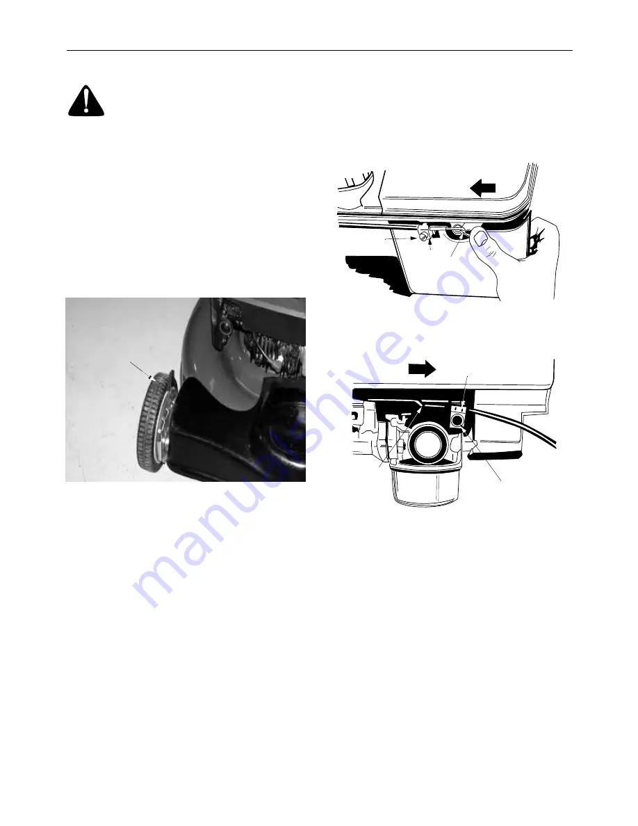
An adjusting plate and lever at each wheel position
provides cutting height adjustment. Each adjusting
plate has nine height positions. Height of cut will be
changed when the lever is moved from one position
to another. Simply depress the lever towards wheel
and move wheel and lever assembly to desired
position. All wheels must be placed in the same
relative position. See Figure 12.

Figure 12  

THROTTLE CONTROL ADJUSTMENT

NOTE: 

Your unit may be a constant speed engine,

which is set at full throttle for best performance. This
engine requires no throttle adjustment.
 
If you have a unit with a the throttle control which
needs adjustment or if it has been replaced, adjust
as follows.

1.

Remove the screw shown in Figure 13. Remove
the cable clamp from the cable.

NOTE: 

 If you have a Tecumseh engine, simply

loosen the screw shown in Figure 14 so the cable
will move freely beneath the clamp. It is not
necessary to remove the screw and clamp
completely.

2.

Push the throttle control lever on the handle all
the way forward as far as it will go, then back it
off one “click.” Make certain the throttle control
lever remains in this position.

3.

Push the control lever on the engine as far
toward the rear of the engine as it will go.
Secure the cable in this position with the cable
clamp and screw.

Figure 13  

Figure 14  

DRIVE CLUTCH ADJUSTMENT

The drive clutch control adjustment wheel is located
in the drive clutch control handle housing and is
used to tighten or loosen the drive belt. You will
have to adjust the drive clutch control if any of the
following happens:

• The mower does not propel itself with the

drive clutch engaged.

• The mower’s drive wheels hesitate with the

drive clutch engaged.

To resolve the above problems, rotate the adjust-
ment wheel with your fingers. Clockwise to tighten
the cable and counter-clockwise to loosen the cable.
See Figure 15.

Height

Adjuster

Lever

Screw

Cable
Clamp Control

Lever on

Engine

Briggs & Stratton Quantum Engines

Control

Lever 

On Engine

Screw

Cable
Clamp

Tecumseh Engines

Summary of Contents for Series 580

Page 1: ...ystem is equipped with a spark arrester meeting applicable local or state laws if any If a spark arrester is used it should be maintained in effective working order by the operator In the State of Cal...

Page 2: ...pets Stop engine when they are in the vicinity of your mower to help prevent blade contact or thrown object injury Although the area of operation should be completely cleared of foreign objects an ob...

Page 3: ...not operate this unit on that area or serious injury could result DO Mow across the face of slopes never up and down Exercise extreme caution when changing direction on slopes Watch for holes ruts hid...

Page 4: ...ularly After striking a foreign object stop the engine remove the wire from the spark plug and thoroughly inspect the mower for any damage Repair the damage before starting and operating the mower Nev...

Page 5: ...not mow on inclines with a slope in excess of 15 degrees a rise of approximately 2 1 2 feet every 10 feet A riding mower could overturn and cause serious injury If operating a walk behind mower on su...

Page 6: ...heses ATTACHING THE STRUTS Hex Bolt Bell Washer Nut 1 4 20 710 0751 736 0270 712 0287 Saddle Washer 320 I D x 83 O D Lock Washer 5 16 736 0119 Nut 5 16 18 712 0267 736 0451 265 I D x 75 O D x 062 A 1...

Page 7: ...t the rear of the deck The model plate will look like Figure 2 Figure 2 SECTION 4 CALLING CUSTOMER SUPPORT If you are having difficulty assembling this product or if you have any question regarding th...

Page 8: ...is observed from the operating position Figure 4 HOW TO SET UP YOUR LAWN MOWER Assembling Handle 1 Remove packing material which may be between the upper and lower handles for shipping purposes 2 Lift...

Page 9: ...ition 3 The rear axle shaft has a right side and a left side The right side has two tabs and the left side has one tab See Figure 6 4 Slide the left side of the rear axle shaft through the right pivot...

Page 10: ...ghtened securely WARNING The shipping chute retainer must be removed and discarded before operating the mower Optional Mulching Baffle A mulching kit OEM 190 110 is available for the mowers shown in t...

Page 11: ...Squeezing the drive clutch control engages the drive mechanism to the wheels Releasing the clutch control stops the wheels from driving Release the drive clutch control to slow down when negotiating...

Page 12: ...t lawn is clear of stones sticks wire or other objects which could damage lawn mower or engine Such objects could be accidentally thrown by the mower in any direction and cause serious personal injury...

Page 13: ...ew shown in Figure 14 so the cable will move freely beneath the clamp It is not necessary to remove the screw and clamp completely 2 Push the throttle control lever on the handle all the way forward a...

Page 14: ...justing carburetor SECTION 10 LUBRICATION WARNING Always stop engine and disconnect spark plug wire before cleaning lubricating or doing any kind of work on lawn mower Figure 16 Blade Control Lubricat...

Page 15: ...lance Before reassembling the blade pulley assembly to the unit lubricate the engine crankshaft and the inner surface of the blade adapter with light oil or engine oil Lubricating the bolt holes bolts...

Page 16: ...ass dirt and combustible debris from muffler area REAR FLAP REPLACEMENT The rear flap is attached to the back of the mower deck and is designed to minimize the possibility that objects will be thrown...

Page 17: ...ease to prevent rusting 4 Store mower in a dry clean area Do not store next to corrosive materials such as fertilizer NOTE When storing any type of power equipment in a poorly ventilated or metal stor...

Page 18: ...ll with fresh fuel Refer to the engine manual packed with your unit Refer to the engine manual packed with your unit Engine overheats Engine oil level low Dirty aircleaner Air flow restricted Carburet...

Page 19: ...rew Hardware 7510042823 Screw Part No 731 1402A 731 1694 731 1695 731 1934 Color Yellow Black Silver Charcoal Part No 7510143208 Color Black Part No 731 1585B Color Black Part No 731 1586B 731 1612A C...

Page 20: ...NGINE MANUAL 31 1 2 3 4 6 7 8 12 15 17 68 13 9 11 10 14 16 20 21 19 18 22 23 24 25 26 28 27 67 66 54 29 30 55 56 61 62 63 64 65 60 59 57 53 52 51 50 44 45 47 48 46 49 41 36 34 36 43 42 33 37 38 39 40...

Page 21: ...e Pulley 36 753 0825 Blade Adapter Kit Incl Ref 34 38 39 40 37 742 0642 Blade 22 742 0742 Mulching Blade 22 38 736 0452 Bell Washer 396 I D x 1 140 O D x 095 39 710 0606 Hex Screw 1 4 2 0x 1 50 40 710...

Page 22: ...51 43 46 47 53 52 42 41 37 40 39 33 34 32 31 30 36 19 20 22 23 24 25 26 27 28 19 20 49 48 29 52 53 54 41 42 55 IMPORTANT For a proper working machine use Factory Approved Parts V BELTS are specially...

Page 23: ...x 625 x 062 26 618 0299 Housing Lwr Includes 27 27 741 0672 Flange Bearing 378 x 531 x 370 28 710 1276 Hex Screw w Wash 1 4 20 x 750 29 618 0298 Transmission Complete Incl 1 thru 30 30 732 0708 Bearin...

Page 24: ...ment of the manufacturer Transportation charges Transportation charges for the movement of any power equipment unit or attachment are the responsibility of the purchaser Units exported out of the Unit...

Reviews:

Related manuals for Series 580