background image

11

Figure 5

5

Maintaining 

Your Lawn 

Mower

WARNING

When removing 
the cutting blade 
for sharpening or 
replacement, protect 
your hands with a 
pair of heavy gloves 
or use a heavy rag to 
hold the blade.

An unbalanced blade 
will cause excessive 
vibration when rotat-
ing at high speeds. It 
may cause damage 
to mower, and could 
break causing per-
sonal injury.

Blade Care

WARNING: When removing the 
cutting blade for sharpening or 
replacement, protect your hands 
with a pair of heavy gloves or use 
a heavy rag to hold the blade.

Periodically inspect the blade adapter for cracks, 
especially if you strike a foreign object. Replace when 
necessary. Follow the steps below for blade service.
1.  Disconnect spark plug wire from spark plug. Turn 

mower on its side making sure that the air filter and 
the carburetor are up.

2.  Remove the bolt and the blade bell support which 

hold the blade and the blade adapter to the engine 
crankshaft. See Figure 4.

3.  Remove blade and adapter from the crankshaft.
4.  The blade can be sharpened with a file or on a grind-

ing wheel. Do not attempt to sharpen the blade while it 
is still on the mower.

5.  When sharpening the blade, follow the original angle 

of grind. Grind each cutting edge equally to keep the 
blade balanced. 

6.  Remove blade from the adapter for testing balance. 
7.  Balance the blade on a round shaft screwdriver to 

check. Remove metal from the heavy side until it 
balances evenly. 

WARNING: An unbalanced blade 
will cause excessive vibration 
when rotating at high speeds. It 
may cause damage to mower, and 
could break causing personal 
injury.

8.  Lubricate the engine crankshaft and the inner surface 

of the blade adapter with light oil. Slide the blade 
adapter onto the engine crankshaft. 

9.  Place the blade on the adapter such that the side 

of the blade marked “Bottom” (or with part number) 
faces the ground when the mower is in the operating 
position. Make sure that the blade is aligned and 
seated on the blade adapter flanges.

10. Place blade bell support on the blade. Align notches 

on the blade bell support with small holes in blade.

11. Replace hex bolt and tighten hex bolt to torque: 450 

in. lbs. min., 600 in. lbs. max.

To ensure safe operation of your mower, periodically 
check the blade bolt for correct torque.

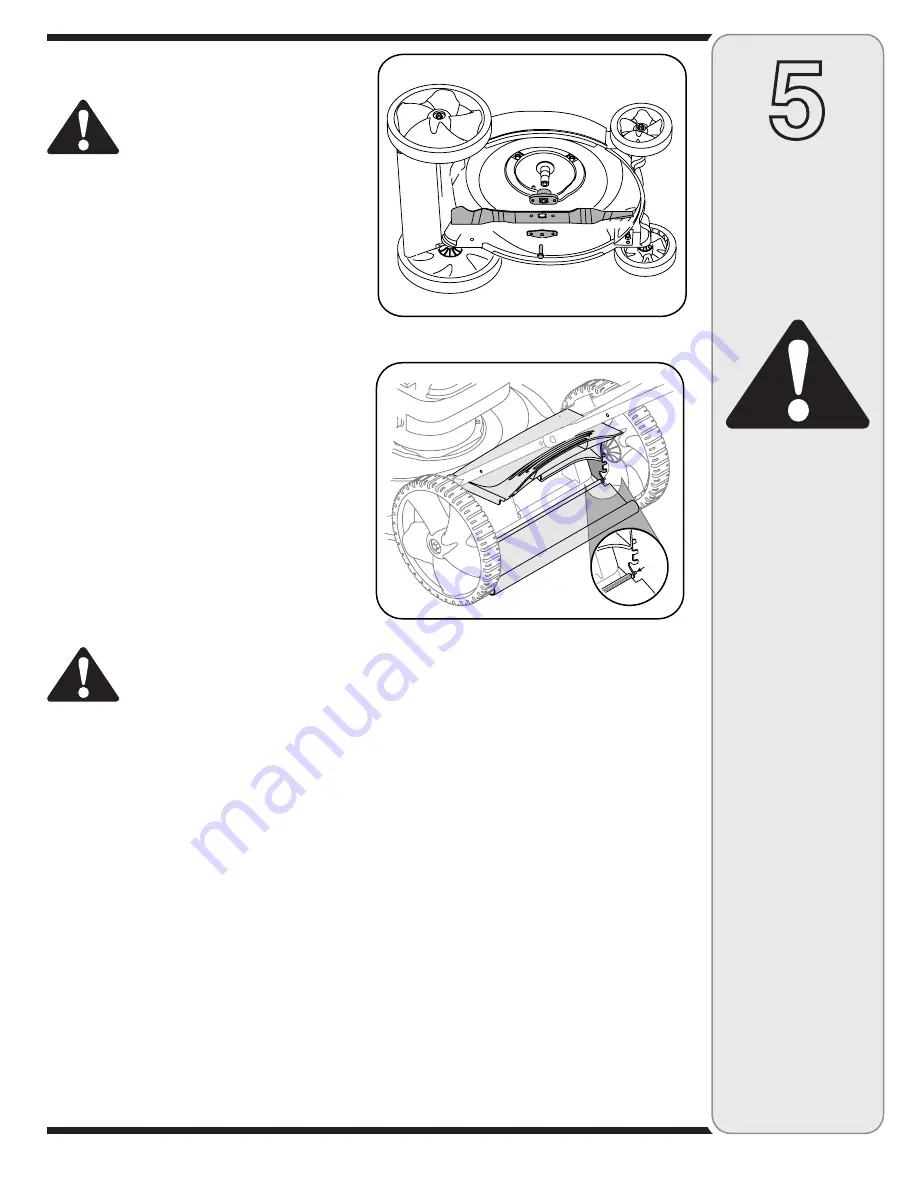
Replacing Rear Flap 

1.  To remove rear flap, cut off the flat end of the wire 

rod which secures it to the deck. See Figure 5. 

2.  Attach the new flap and new rod to deck, bending 

the ends of the new rod over to secure to deck.

Off-Season Storage

The following steps should be taken to prepare your 
lawn mower for storage.
1.  Clean and lubricate mower thoroughly as described 

in the lubrication instructions.

2.  We do not recommend the use of a pressure washer 

or garden hose to clean your unit.

3.  Refer to engine manual for correct engine  

storage instructions.

4.  Coat mower’s cutting blade with chassis grease to 

prevent rusting.

5.  Store mower in a dry, clean area. Do not store next 

to corrosive materials, such as fertilizer.

When storing any type of power equipment in a poorly 
ventilated or metal storage shed, care should be taken 
to rust-proof the equipment. Using a light oil or silicone, 
coat the equipment, especially cables and all moving 
parts of your lawn mower before storage.

Figure 4

Wire


Rod

Summary of Contents for Yard-Man 588

Page 1: ...ntained in effective working order by the operator In the State of California the above is required by law Section 4442 of the California Public Resources Code Other states may have similar laws Feder...

Page 2: ...Customer Support If you have difficulty assembling this product or have any questions regarding the controls operation or maintenance of this unit you can seek help from the experts Choose from the o...

Page 3: ...lk behind mower on such a slope it is extremely difficult to maintain your footing and you could slip resulting in serious injury Operate RIDING mowers up and down slopes never across the face of slop...

Page 4: ...shirts Shirts and pants that cover the arms and legs and steel toed shoes are recommended Never operate this machine in bare feet sandals slippery or light weight e g canvas shoes 8 Do not put hands...

Page 5: ...hile engine is hot or running Allow engine to cool at least two minutes before refueling 10 Never over fill fuel tank Fill tank to no more than inch below bottom of filler neck to provide for fuel exp...

Page 6: ...control handle against upper handle b Pull starter rope out of the engine Release blade control handle c Slip starter rope into rope guide d Tighten wing nut 4 Insert post on cable ties into holes pro...

Page 7: ...he grass catcher a Place bag over frame so that its black plastic side is at the bottom b Slip plastic channel of grass bag over hooks on the frame See Step 7 All the plastic channels except center to...

Page 8: ...rter is attached to the right upper handle Stand behind the unit and pull the recoil starter rope to start the unit Gas and Oil Fill Up 1 Check oil level and add oil if necessary Follow engine manual...

Page 9: ...for the blade to stop completely before doing any work on the mower or to remove the grass catcher Stopping Engine 1 Release blade control to stop the engine and blade 2 Disconnect spark plug wire fr...

Page 10: ...igure 3 4 Follow the accompanying engine manual for lubrica tion schedule and instruction for engine lubrication Deck Care Clean underside of the mower deck after each use to prevent build up of grass...

Page 11: ...ge to mower and could break causing personal injury 8 Lubricate the engine crankshaft and the inner surface of the blade adapter with light oil Slide the blade adapter onto the engine crankshaft 9 Pla...

Page 12: ...retor out of adjustment Engine overheats 1 Fill crankcase with proper oil 2 Remove blower housing and clean 3 Refer to engine manual 1 Engine oil level low 2 Air flow restricted 3 Carburetor not adjus...

Page 13: ...13 7 Safety Labels WARNING DO NOT remove safety or any labels from mower for any reason...

Page 14: ...14 39 38 41 10 17 46 47 19 40 30 44 12 30 24 32 18 32 25 27 45 22 21 43 23 26 15 28 29 45 42 16 14 4 8 3 2 33 20 6 7 9 11 5 1 13 37 34 35 45 45 31 36...

Page 15: ...m Assembly LH 26 736 0524B Blade Bell Support 27 787 01290 Front Adjustment Plate 28 720 0426 Adjustment Lever Knob 29 732 0866 Spring Lever 30 738 0507B Shoulder Screw 31 734 04086 Front Wheel 7 x 1...

Page 16: ...the exterior finish due to use or exposure d Service completed by someone other than an authorized service dealer e MTD does not extend any warranty for products sold or exported outside of the United...

Reviews: