dV E-Series Technical Reference Manual 208V – 600V
Form: DVT-TRM-E December 2021 Rev. 001 20
Grounding
NOTE: For cable shield grounding follow the drive manufacturer’s recommendations.
Power Wiring Connection
Verify that the power source to which the filter is to be connected is in agreement with the
nameplate data on the filter. A fused disconnect switch or circuit breaker should be installed
between the filter and its source of power in accordance with the requirements of the NEC and
all local electrical codes and regulations. Refer to the drive user manual for selection of the
correct fuse rating and class.
For part numbers starting with
DVTK
, interconnection between the reactor, resistor, drive, and
motor is shown in Figure 5-2: Kit Diagram
.
For part numbers starting with
DVTP
,
DVTG
, or
DVTW
, interconnection between the filter, drive,
and motor is shown in Figure 5-3: Open Panel and Enclosed Diagram
.
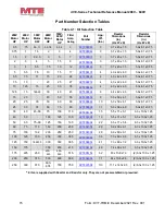
Wire gauge range and terminal torque requirements for the dV E-Series are shown in Table 5-1:
.
Refer to the drive user manual for instructions on interconnecting the drive and motor and the
correct start-up procedures for the drive.
The filter is designed for use with copper conductors with a minimum temperature rating of 75
degrees C.
WARNING
The filter must always be grounded with a grounding conductor connected to
ground terminals.
For panel mounted units, ensure a 2” x 2” area is cleaned of paint and varnish
on lower mounting bracket for ground connection.
WARNING
Input and output power wiring to the filter should be performed by authorized
personnel in accordance with the NEC and all local electrical codes and
regulations.
Cable lugs and mounting hardware are provided by the customer.
Any extremely low or high resistance readings indicate miswiring and may result
in damage to filter components if not corrected.
On NEMA 3R enclosures, CAB-26AP and larger, no live parts shall be mounted
below 8 inches from the bottom of the enclosure.


