background image

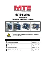
dV E-Series Technical Reference Manual 208V – 600V 

         Form: DVT-TRM-E December 2021 Rev. 001 

2. GENERAL INFORMATION 


The purpose of the manual is to properly specify size, install, interconnect, and operate the dV 

E-Series motor protection filter. 


For most current information, please refer to website 

https://www.mtecorp.com/products/dv-e-series/


This manual is intended for use by personnel experienced in the operation and maintenance of 

inverters. Because of the high voltages required by the filter, inverter, and the potential dangers 

presented by rotating machinery, it is essential that all personnel involved in the operation and 

maintenance of this filter know and practice the necessary safety precautions for this type of 

equipment. Personnel should read and understand the instructions contained in this manual 

before installing, operating, or servicing the filter and inverter to which it is connected. 


Receipt & Repair Statement 


Upon Receipt of this Filter:


The dV E-Series motor protection filter has been subjected to demanding factory tests before 

shipment. Carefully inspect the shipping container for damage that may have occurred in transit. 

Then unpack the filter and carefully inspect for any signs of damage. Save the shipping 

container for future transport of the filter. 


In the event of damage, please contact and file a claim with the freight carrier involved 

immediately. 


If the equipment is not going to be put into service upon receipt, cover and store the filter in a 

clean, dry location. After storage, ensure that the equipment is dry and that no condensation or 

dirt has accumulated on the internal components of the filter before applying power. 


Repair/Exchange Procedure:


MTE Corporation requires a Return Material Authorization Number and form before we can 

accept any filters that qualify for return or repair. If problems or questions arise during 

installation, setup, or operation of the filter, please contact MTE for assistance at: 


Toll Free: 1-800-455-4MTE (1-800-455-4683) 


International Tel: (+1) 262-253-8200 


Fax: 262-253-8222


Summary of Contents for dV E Series

Page 1: ...WARNING High Voltage Only a qualified electrician can carry out the electrical installation of this filter Quick Reference Performance Data Pages 9 12 Selection Guide Pages 13 18 Installation Guide P...

Page 2: ...This page intentionally left blank...

Page 3: ...E SPECIFICATIONS 9 FILTER EFFICIENCY WATT LOSS 10 PERFORMANCE CHART 11 ALTITUDE DERATING 12 MOTOR FREQUENCY DERATING 12 4 HOW TO SELECT 13 SELECTION GUIDE 13 UNDERSTANDING THE DV E SERIES PART NUMBER...

Page 4: ...12 Figure 5 1 Basic Schematic Diagram 21 Figure 5 2 Kit Diagram 22 Figure 5 3 Open Panel and Enclosed Diagram 23 List of Tables Table 3 1 Performance Specifications 9 Table 3 2 Filter Efficiency Watt...

Page 5: ...volved Failure to use proper precautions may lead to serious injury or death WARNING General Warning warns of situations that can result in serious injury or death if proper precautions are not used C...

Page 6: ...al Code NEC or governing authority Even if the upstream disconnect protection device is open the drive down stream of the filter may feedback high voltage to the filter The drive safety instructions m...

Page 7: ...tatement Upon Receipt of this Filter The dV E Series motor protection filter has been subjected to demanding factory tests before shipment Carefully inspect the shipping container for damage that may...

Page 8: ...e protection against contact with the enclosed equipment Type 2 NEMA IEC IP20 Enclosure Are designed for indoor use and will provide protection against contact with the enclosed equipment and provide...

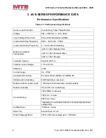
Page 9: ...40C to 60C Modular Filter 40C to 50C Enclosed Filter 40C to 90C Storage Insulation System Class N 200 C Insertion Loss Voltage 1 7 at 60 Hz Efficiency 99 Current range 3A 750A Available form factors K...

Page 10: ...Power Dissipation Watts 3 99 0 51 4 99 0 54 7 99 0 64 9 99 0 70 12 99 0 86 17 99 0 111 22 99 0 97 27 99 0 95 35 99 0 91 45 99 0 76 55 99 0 102 65 99 0 152 80 99 0 122 110 99 0 92 130 99 0 113 160 99 0...

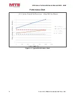
Page 11: ...dV E Series Technical Reference Manual 208V 600V 11 Form DVT TRM E December 2021 Rev 001 Performance Chart Figure 3 1 Typical Performance Chart...

Page 12: ...Technical Reference Manual 208V 600V Form DVT TRM E December 2021 Rev 001 12 Altitude Derating Figure 3 2 Altitude Derating Curve Motor Frequency Derating Figure 3 3 Current Derating for Drive Output...

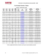
Page 13: ...d 3R mechanical configurations Please verify information below for proper selection Lead Length This product is suitable for applications with motor leads up to 1 000 ft Contact MTE Application Engine...

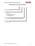
Page 14: ...December 2021 Rev 001 14 Understanding the dV E Series Part Number DVT X _ _ _ _ E dV E Series Filter Type K Kit P Open Panel G General Purpose NEMA 1 2 W Weather NEMA 3R Current Rating i e 0003 is 3...

Page 15: ...0 75 10 12 5 15 25 30 35 DVTK0035E 4 4 0 x 4 2 x 4 0 5 0 x 8 1 x 0 75 12 5 15 18 5 22 30 40 45 DVTK0045E 6 4 4 x 4 2 x 4 0 5 0 x 8 1 x 0 75 15 20 40 50 55 DVTK0055E 8 5 0 x 5 9 x 4 3 5 0 x 8 1 x 0 75...

Page 16: ...9 x 5 5 x 8 0 10 12 5 15 25 30 35 DVTP0035E 9 12 0 x 8 0 x 8 1 12 5 15 18 5 22 30 40 45 DVTP0045E 11 12 0 x 8 0 x 8 1 15 20 40 50 55 DVTP0055E 12 12 0 x 8 0 x 9 0 20 25 30 50 60 65 DVTP0065E 14 12 0...

Page 17: ...13 2 x 13 0 x 13 1 10 12 5 15 25 30 35 DVTG0035E 21 13 2 x 13 0 x 13 1 12 5 15 18 5 22 30 40 45 DVTG0045E 23 13 2 x 13 0 x 13 1 15 20 40 50 55 DVTG0055E 25 13 2 x 13 0 x 13 1 20 25 30 50 60 65 DVTG006...

Page 18: ...5 x 11 0 x 12 0 10 12 5 15 25 30 35 DVTW0035E 31 15 5 x 11 0 x 12 0 12 5 15 18 5 22 30 40 45 DVTW0045E 33 15 5 x 11 0 x 12 0 15 20 40 50 55 DVTW0055E 66 24 0 x 12 5 x 23 0 20 25 30 50 60 65 DVTW0065E...

Page 19: ...requirements of the enclosure include the power dissipation of the filter along with all the other components located in the panel A general guideline is to allow a side clearance of four 4 inches an...

Page 20: ...d Enclosed Diagram p23 Wire gauge range and terminal torque requirements for the dV E Series are shown in Table 5 1 Torque Ratings p24 Refer to the drive user manual for instructions on interconnectin...

Page 21: ...dV E Series Technical Reference Manual 208V 600V 21 Form DVT TRM E December 2021 Rev 001 Basic Schematic Diagram Figure 5 1 Basic Schematic Diagram...

Page 22: ...dV E Series Technical Reference Manual 208V 600V Form DVT TRM E December 2021 Rev 001 22 Interconnection Diagram Kit Figure 5 2 Kit Diagram...

Page 23: ...dV E Series Technical Reference Manual 208V 600V 23 Form DVT TRM E December 2021 Rev 001 Interconnection Diagram Open Panel and Enclosed Figure 5 3 Open Panel and Enclosed Diagram...

Page 24: ...2x or 3 0 N A 14 16 250 1 2x or 250kcmil N A 14 16 305 2 0 2x N A 14 16 365 3 0 2x N A 14 16 415 4 0 2x N A 14 16 515 300kcmil 2x N A 14 16 600 350kcmil 2x N A 14 16 750 N A 14 16 NOTE Kit versions of...

Page 25: ...ter installation ensure that All filter ground terminals are connected to ground Power wiring to the utility drive filter and motor is in accordance with the power wiring connection diagrams shown in...

Page 26: ...ly and in accordance with OSHA Regulations High voltage is used in the operation of this filter Use Extreme caution to avoid contact with high voltage when operating installing or repairing this filte...

Page 27: ...tage and shutdown parameters are valid PROBLEM dV E Series filter runs Hot Possible cause Normal operation reactor 150 C and resistors 300 C Solution Caution Parts are very hot and may cause burns Fol...

Reviews: