background image


HYDROCAL 1001+ Installation and operation manual 

Page 2/76 

4.3.1.6.


 LED bar level - Gas .................................................... 34


4.3.1.7.


 LED bar levels - Moisture ........................................... 46


4.3.2.


Special Operation ........................................................................................................ 47


4.3.2.1.


Unit Power-On - Boot ........................................................................................... 47


4.3.2.2.


Update of Firmware - Downloader ........................................................................ 48


4.3.2.3.


Update of Firmware - via TFTP ............................................................................. 50


4.3.2.4.


Functional Test ..................................................................................................... 51


4.3.2.5.


Test Mode ............................................................................................................ 53


4.3.3.


Communication Interface Reset ................................................................................... 56


4.4.


Default Communication Interface Setup.............................................................................. 57


4.5.


Establish a Point-to-Point Ethernet Connection .................................................................. 58


4.5.1.


Setup HYDROCAL 1001+ ........................................................................................... 58


4.5.2.


Change of TCP/IP Settings on the PC ......................................................................... 58


4.5.2.1.


Navigating to the Network Adapter Properties ...................................................... 59


4.5.2.2.


Changing the Network Adapter Properties ............................................................ 61


4.5.3.


Test of Communication with Hydrosoft ........................................................................ 62


4.5.4.


Diagnosis / Trouble Shooting ....................................................................................... 63


4.5.4.1.


Basic Checks ........................................................................................................ 63


4.5.4.2.


Check of PC Network Adapter Setup .................................................................... 63


4.5.4.3.


Low Level Connection Test (PING) ...................................................................... 64


4.6.


Communication setup ......................................................................................................... 65


4.6.1.


RS485 setup ................................................................................................................ 65


4.6.1.1.


Point-to-Point ........................................................................................................ 65


4.6.1.2.


Bus Node ............................................................................................................. 66


4.6.1.3.


MODBUS RTU ..................................................................................................... 67


4.6.1.4.


MODBUS ASCII ................................................................................................... 68


4.6.2.


ETHERNET setup ....................................................................................................... 69


4.6.2.1.


Static IP ................................................................................................................ 69


4.6.2.2.


DHCP Client ......................................................................................................... 70


4.6.3.


MODBUS

®

 TCP ........................................................................................................... 71


4.6.3.1.


Function, Register and Address Mapping ............................................................. 71


5.


Technical data ....................................................................................................................... 73


6.


Dimensional Drawings .......................................................................................................... 75


6.1.


Dimensions of valve connection ......................................................................................... 76


6.1.1.


Connection thread G 1½’’ ISO DIN 228-1 .................................................................... 76


6.1.2.


Connection thread 1½’’ NPT ANSI B 1.20.1 ................................................................ 76


Summary of Contents for HYDROCAL 1001 Plus

Page 1: ...HYDROCAL 1001 Installation and operation manual Edition RS485 01 2015 HYDROCAL 1001 Composite Gas in Oil Sensor with Moisture in Oil Measurement Installation and operation manual...

Page 2: ...Vor dem Hassel 2 D 21438 Brackel Germany Phone 49 4185 5857 0 Fax 49 4185 5857 68 Email info emh de Copyright MTE Meter Test Equipment AG All rights reserved The contents of this manual are subject to...

Page 3: ...nstallation 11 2 4 1 2 Indirect installation 12 2 4 2 Electrical connection 14 2 4 3 Putting into operation 15 3 Hardware components 16 3 1 Front view 16 3 2 Rear view 17 3 3 Connections of measuremen...

Page 4: ...g to the Network Adapter Properties 59 4 5 2 2 Changing the Network Adapter Properties 61 4 5 3 Test of Communication with Hydrosoft 62 4 5 4 Diagnosis Trouble Shooting 63 4 5 4 1 Basic Checks 63 4 5...

Page 5: ...L 1001 is equipped with 2 analog 0 4 20 mA outputs for the dissolved composite gas in oil and moisture in oil analysis results and 4 digital relay outputs Gas high alarm gas high high alarm moisture a...

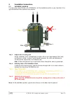
Page 6: ...se this position only if a continuous oil flux through the cooler is guaranteed Pos 2 Draining valve on the transformer tank The flange of the draining valve must be at minimum height of 40 cm in orde...

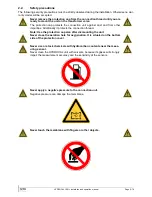
Page 7: ...other impurities Additionally it protects the connection thread Note Use the protection cap also after dismounting the unit Never close the aeration hole for oxygenation It is situated on the bottom s...

Page 8: ...ge the membrane Never install or remove the HYDROCAL unit without opening the aeration screw first Never use galvanized fittings or valves to mount the HYDROCAL unit Galvanized fittings or valves can...

Page 9: ...ese locking elements are usually provided with a blind flange Therefore they must be upgraded before mounting the HYDROCAL unit with a corresponding threaded flange connection adapter or a fitting wit...

Page 10: ...nit can be executed with following tools and utilities Long Allen key No 4 Aeration screw bleeding screw Digital Multimeter Checking supply voltage Screw driver No 2 Main connectors supply voltage cab...

Page 11: ...is applied before the actual thread adhesive LOCTITE 577 is applied on 3 to 4 turns of the external thread of the HYDROCAL connection unit Attention Please follow the instructions of the manufacturer...

Page 12: ...rect installation 2 4 1 2 Note In case there are strong vibrations on the connection valve the valve should be relieved by a support A good oil flux should exist on the installation position If necess...

Page 13: ...ean the outer thread of the connection unit with a dry cleaning rag or paper towel Remove any remaining of thread sealing tape completely from the threads For persistent remaining you can use the bras...

Page 14: ...with a dry cleaning rag or paper towel from the unit Attention Do not use solvents for cleaning Check after 30 minutes if the threaded connection is tight no leakage 2 4 1 2 Indirect installation Indi...

Page 15: ...g to the company procedures Work carefully in order to prevent air entering into the transformer Use a bucket to catch the leaking oil Slowly open the transformer valve until oil runs out of the provi...

Page 16: ...ust be used for all cables 1x M20 SKINTOP cable gland Clamping range 7 0 13 0 mm 1x M25 SKINTOP cable gland Clamping range 9 0 17 0 mm Attention For cables with a smaller diameter please use reducing...

Page 17: ...for alarm and analog outputs cable Cable type LFLEX FD855CP or equivalent Cable diameter 13 3 mm Cross section 0 5 mm2 of 16 internal wires 2 4 3 Putting into operation When the supply voltage for th...

Page 18: ...nts 3 1 Front view The front consists of the following components 1 Protection cover with aeration hole 2 Knurled thumb screw to fasten the protection cover 3 Function LED of external user interface 4...

Page 19: ...HYDROCAL 1001 Installation and operation manual Page 17 76 3 2 Rear view 1 Oil unit with connection thread G 1 DIN ISO 228 1 or 1 NPT ANSI B 1 20 1...

Page 20: ...ges on request Power consumption max 250 VA Micro fuse at 120V T3 15A Micro fuse at 230V T2A Connect the supply voltage cable as followed AC Version Phase L Protection earth PE Neutral N DC Version Pl...

Page 21: ...n conjunction with the reset button 3 LED bar level Moisture Moisture concentration indication with 3 single color LEDs 4 LED bar level Gas Gas concentration indication with 4 single color LEDs 5 Anal...

Page 22: ...are mounted directly on the measurement and controller card must be specified when ordering 13 Jumper J1 Function relay contact when system is okay relay is switched on The function relay output can o...

Page 23: ...alog output 2 Moisture concentration X1 7 AO2 Analog output 2 GNDio Note Free assignment for both analog outputs 12 Connection terminal X2 Relay outputs Connection for relay outputs 220 VDC VAC 2 A 60...

Page 24: ...nt and controller card contains a beeper for additional acoustic signalization The beeper has three different beep sounds which vary in lengths and sound form Icon Description Short constant beep Long...

Page 25: ...2 not connected X1 3 Neutral N Blue X1 4 not connected X1 5 Phase L Black or brown X1 6 not connected X1 7 Heating resistor connection Red X1 8 not connected Note The connection terminal X1 is underne...

Page 26: ...state relay varies between supply voltage type AC and DC For AC supply voltages the solid state relay crydom D2410 AC 10 A is used left For DC supply voltages the solid state relay crydom D5D07 DC 7 A...

Page 27: ...HYDROCAL 1001 Installation and operation manual Page 25 76 3 5 1 Wiring heating resistors for 230 V Note The solid sate relay must correspond to the supply voltage type AC or DC...

Page 28: ...HYDROCAL 1001 Installation and operation manual Page 26 76 3 5 2 Wiring heating resistors for 120 V Note The solid sate relay must correspond to the supply voltage type AC or DC...

Page 29: ...al user interface 4 3 4 2 External user interface The external user interface is located on the component side of the measurement and controller card and is facing toward the front of the HYDROCAL uni...

Page 30: ...relay out put 1 for level 1 High alarm connection terminal X2 1 2 and the relay output 2 for level 2 High High alarm connection terminal X2 3 4 The multicolor LED illustrates the general status only...

Page 31: ...l Page 29 76 Gas concentration Icon Color sequence absolute daily trend weekly trend 0 0 0 1 0 0 2 0 0 0 1 0 0 2 0 1 1 0 1 2 0 2 1 0 2 2 0 0 0 1 0 0 2 1 0 1 1 0 2 2 0 1 2 0 2 0 1 1 0 1 2 0 2 1 0 2 2 1...

Page 32: ...2 200 Delay 1 s 86400 or 1 0 00 00 Delay 2 s 172800 or 2 0 00 00 Action 1 Output Hold Action 2 Output Hold These settings can be modified in Hydrosoft alarm setup 4 2 3 Moisture LED The HYDROCAL unit...

Page 33: ...special operations the LEDs are used in another manner to reflect the status or progress of the related task The icons of the single color LEDs green or red have the following signification Icon Descr...

Page 34: ...e LED energy save mode 4 3 1 2 LED Ethernet The Ethernet communication interface is represented by a red and a green single color LED The LEDs illustrates the status of the Ethernet communication inte...

Page 35: ...s on s off output current 16 mA off s on s off output current 16 mA Sensor signal for analog output not available not defined 4 3 1 5 LED Moisture analog output The status and the actual value of the...

Page 36: ...atus will be illus trated with the same 4 LEDs The LEDs illustrates the status of the gas concentration absolute as follow Description Gas sensor not active measurement function stopped Gas concentrat...

Page 37: ...HYDROCAL 1001 Installation and operation manual Page 35 76 Gas concentration Color sequence LED bar level absolute daily trend weekly trend 0 0 0 1 0 0 2 0 0 3 0 0 0 1 0 0 2 0 0 3 0...

Page 38: ...HYDROCAL 1001 Installation and operation manual Page 36 76 Gas concentration Color sequence LED bar level absolute daily trend weekly trend 0 0 1 0 0 2 0 0 3 0 1 1 0 1 2 0 1 3...

Page 39: ...HYDROCAL 1001 Installation and operation manual Page 37 76 Gas concentration Color sequence LED bar level absolute daily trend weekly trend 0 2 1 0 2 2 0 2 3 0 3 1 0 3 2 0 3 3...

Page 40: ...HYDROCAL 1001 Installation and operation manual Page 38 76 Gas concentration Color sequence LED bar level absolute daily trend weekly trend 1 1 0 1 2 0 1 3 0 2 1 0 2 2 0 2 3 0...

Page 41: ...HYDROCAL 1001 Installation and operation manual Page 39 76 Gas concentration Color sequence LED bar level absolute daily trend weekly trend 3 1 0 3 2 0 3 3 0 1 0 1 1 0 2 1 0 3...

Page 42: ...HYDROCAL 1001 Installation and operation manual Page 40 76 Gas concentration Color sequence LED bar level absolute daily trend weekly trend 2 0 1 2 0 2 2 0 3 3 0 1 3 0 2 3 0 3...

Page 43: ...HYDROCAL 1001 Installation and operation manual Page 41 76 Gas concentration Color sequence LED bar level absolute daily trend weekly trend 1 1 1 1 1 2 1 1 3 1 2 1 1 2 2 1 2 3...

Page 44: ...HYDROCAL 1001 Installation and operation manual Page 42 76 Gas concentration Color sequence LED bar level absolute daily trend weekly trend 1 3 1 1 3 2 1 3 3 2 1 1 2 1 2 2 1 3...

Page 45: ...HYDROCAL 1001 Installation and operation manual Page 43 76 Gas concentration Color sequence LED bar level absolute daily trend weekly trend 2 2 1 2 2 2 2 2 3 2 3 1 2 3 2 2 3 3...

Page 46: ...HYDROCAL 1001 Installation and operation manual Page 44 76 Gas concentration Color sequence LED bar level absolute daily trend weekly trend 3 1 1 3 1 2 3 1 3 3 2 1 3 2 2 3 2 3...

Page 47: ...s for LED bar level gas concentration absolute are Level 1 100 Level 2 500 Level 3 1000 Note The standard settings for LED bar level gas concentration daily trend are Level 1 10 Level 2 50 Level 3 100...

Page 48: ...The moisture concentration has 2 configura ble levels level 1 2 and their status will be illustrated with the 3 LEDs The LED bar levels for moisture concentration are illustrated as follow Description...

Page 49: ...date of Firmware Downloader 4 3 2 2 Update of Firmware via TFTP 4 3 2 3 Functional Test 4 3 2 4 Test Mode 4 3 2 5 4 3 2 1 Unit Power On Boot After power on or reset of the unit all red LEDs are turned...

Page 50: ...unit switches to a spe cial mode the so called downloader This status can be recognized by the following special LED pattern 2 red LEDs are turned on and 1 green LED is circulating counter clockwise...

Page 51: ...e EEPROM optional writing and verifying the new firmware Each step brings up one additional red LED with the green LEDs being used as a progress bar restarted in each operation If an error occurs all...

Page 52: ...not visualized The subsequent write and verify operation is indicated by two or three red LEDs with the green LEDs used as a progress bar A successful update is followed by an automatic reboot of the...

Page 53: ...internal and external user interface Return to normal operation To invoke the functional test press and hold the reset button until 1 5 beeps have occurred the 1st short beep is committing the presse...

Page 54: ...i with Jumper J1 on Pos 2 J1 2 3 i Relay output 1 X2 1 2 j j Relay output 2 X2 3 4 k k Relay output 3 X2 5 6 l III LEDs of internal and external user interface All LEDs ON l Internal user interface E...

Page 55: ...Gas high alarm Relay output 1 X2 1 2 Test Gas high high alarm Relay output 2 X2 3 4 Test Moisture alarm Relay output 3 X2 5 6 Return to normal operation To invoke the test mode press and hold the test...

Page 56: ...n actual value 1 x 1 of 6 Red on green off 0 1 x 5 x 2 of 6 Red off green on 4 1 x 5 x 3 of 6 Red off green 1 s on 1 s off 8 1 x 5 x 4 of 6 Red off green s on s off 12 1 x 5 x 5 of 6 Red off green s o...

Page 57: ...X2 3 4 1 x 1 of 2 Red color contact open X2 3 4 1 x 5 x 2 of 2 Green color contact closed X2 3 4 1 x 5 x e V Test Moisture alarm Step Description Relay contact e White color contact open X2 5 6 1 x 1...

Page 58: ...ter the long commitment beep press and hold the test button until 1 5 beeps have occurred the 1st short beep is committing the pressed button pause then 4 short beeps and the last beep is longer and o...

Page 59: ...lowing default setup of the communication interfaces RS485 Settings 19200 Baud 8 Bit No Parity 1 Stop Answer delay 0 ms no delay MODBUS off Bus Mode point to point Ethernet DHCP activated DHCP Client...

Page 60: ...o valid but are not in the scope of this description 4 5 1 Setup HYDROCAL 1001 As described before the HYDROCAL 1001 comes with an activated DHCP option by default DHCP is a service in local area netw...

Page 61: ...on and operation manual Page 59 76 4 5 2 1 Navigating to the Network Adapter Properties Open the Start Menu and activate the Control Panel In Control Panel enter Network and Internet Next enter the Ne...

Page 62: ...manual Page 60 76 Click on Change adapter settings The list of available network adapters appears Depending on the configuration of the PC one or more items may be present The network adapter used to...

Page 63: ...ntext menu and choose the bottom level entry Properties The properties page for the network adapter is coming up Click into the list in the middle of the dialog and highlight the entry for Internet Pr...

Page 64: ...on Note A potentially upcoming Windows Network Diagnostics dialog can be closed 4 5 3 Test of Communication with Hydrosoft To test the communication the HYDROCAL unit and the PC are connected via an E...

Page 65: ...tional verify by connecting PC to LAN Rules for IP address setup are followed 4 5 4 5 4 2 Check of PC Network Adapter Setup Make sure the PC has chosen the alternate TCP IP Settings Navigate to the ne...

Page 66: ...m a greyed text Search programs and files is shown in the field on entry Start the command interpreter cmd also called DOS window by pressing enter In the command interpreter type the following and ex...

Page 67: ...ary protocol Bus node 4 6 1 2 PC to several HYDROCAL unit proprietary protocol MODBUS RTU 4 6 1 3 PC to several HYDROCAL units MODBUS RTU protocol MODBUS ASCII 4 6 1 4 PC to several HYDROCAL units MOD...

Page 68: ...ch HYDROCAL unit Mode Off no Modbus activated Address 1 254 enter unique address for each unit Answer Delay 0 ms depending on the used RS485 adapter Serial Setup 19200 2400 115200 Note As soon the add...

Page 69: ...ntered in the following menu Mode RTU Mode Address 1 247 Answer Delay 50 ms Serial Setup 19200 2400 115200 Bauderate 8 7 8 Data Bits N None Odd Even Paritiy 1 1 2 Stop Bits Note A unique address 1 247...

Page 70: ...entered in the following menu Mode ASCII Mode Address 1 247 Answer Delay 50 ms Serial Setup 19200 2400 115200 Bauderate 7 7 8 Data Bits N None Odd Even Paritiy 1 1 2 Stop Bits Note A unique address 1...

Page 71: ...etwork settings can be obtained from your corresponding system administrator IP Address Mask The setting 255 255 255 0 can be used in general Gateway Normally the automatic assigned setting can be use...

Page 72: ...work admin istrator must allow the automatic TCP IP address assignment for HYDROCAL in the network The data in the tree structure which is newly created or modified has to be stored with the button th...

Page 73: ...nsor assignment is given by the proprietary command SNSR see below the mapping table The sensor value is transmitted as a signed inte ger Prior to transmission the real reading is mul tiplied by 10 to...

Page 74: ...ms 0x06 Write Single Register 2000 7D0 42001 Switch MODBUS protocol off MODBUS off It is now possible to switch the MODBUS protocol off via MODBUS This is done by writing 0x00FF like OFF 0x03 Read Hol...

Page 75: ...NSI B 1 20 1 Safety CE certified Isolation protection IEC 61010 1 2002 Degree of protection IP 55 Measurements Gas in oil measurement Measuring quantity Range Accuracy 2 3 TDCG Contribution TDCG 0 5 0...

Page 76: ...principle Diffusion principle with gas permeable TEFLON membrane Fuel cell gas sensor for H2 CO CH4 C2H2 C2H4 and C2H6 Thin film capacitive moisture sensor for H2O measurement Notes 1 120 V 120 V 20 9...

Page 77: ...HYDROCAL 1001 Installation and operation manual Page 75 76 6 Dimensional Drawings...

Page 78: ...HYDROCAL 1001 Installation and operation manual Page 76 76 6 1 Dimensions of valve connection 6 1 1 Connection thread G 1 ISO DIN 228 1 6 1 2 Connection thread 1 NPT ANSI B 1 20 1...

Reviews: