Matrix
®
E-Series Technical Reference Manual 380V – 480V
15
Form: MAE-TRM-E September 2020 REV. 001
5. HOW TO INSTALL
Installation Checklist
WARNING
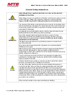
Prior to installation, please refer to all general warnings on pages 1 & 2. Failure
to practice this can result in bodily injury!
Input and output wiring to the filter should be performed by authorized personnel
in accordance with NEC and all local electrical codes and regulations.
WARNING
The filter is designed for use with copper conductors with a minimum
temperature rating of 75 degrees C.
CAUTION
FAN COOLING
For units 21 Amps and above: Proper cooling airflow must be provided at
a minimum of 400 linear feet/min.
Matrix E-Series filters are supplied in the following configuration(s):
•
Open Panel (Modular): Open panel units consist of a reactor and one or more capacitors.
Additional wiring between the reactor and capacitor is required by the customer.
Open panel Matrix E-Series filters are designed for mounting within the customer’s enclosure. When
determining the internal temperature rise and cooling requirements of the enclosure, include the power
dissipation of the filter along with all the other components located in the enclosure. A general guideline
is to allow a side clearance of four (4) inches and a vertical clearance of six (6) inches for proper heat
dissipation and access with the enclosure.
For units 21 Amps and above, proper cooling airflow must be provided at a minimum of 400
linear feet/min.
Do not install in or near a corrosive environment.
Avoid locations where the filter would be subjected to excessive vibrations.
Locate the filter in the lowest temperature regions of the enclosure – generally toward the bottom and
away from high temperature components.
Refer to Article 430 Table 430.91 of the National Electrical code for the selection of the appropriate
enclosure Type Number for your application.


