background image

Sine Wave 2-8 kHz Series A Filter 


  31 

Part No. INSTR-020   REL. 080310


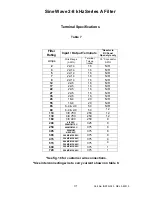
Terminal Specifications 


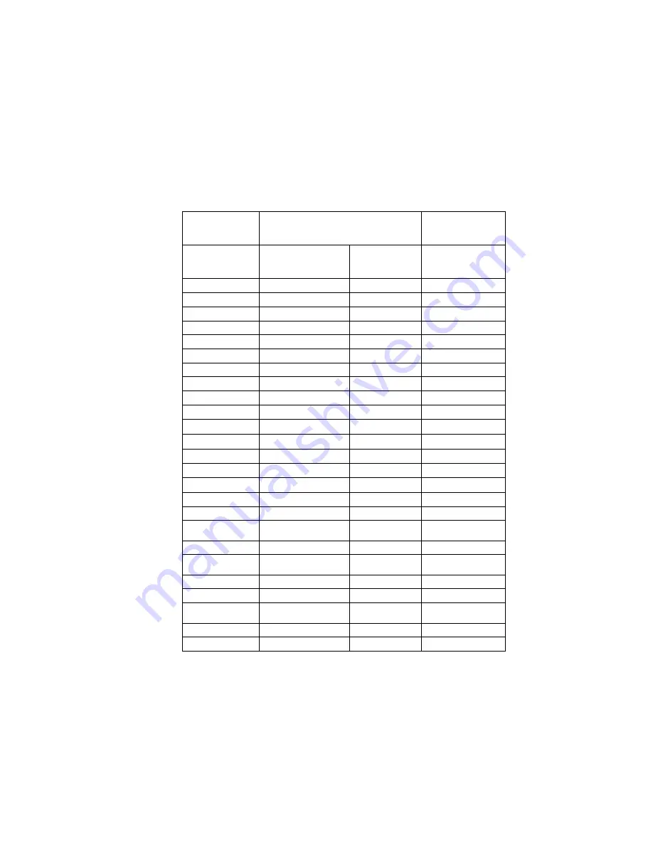
Table 7 


Filter 

Rating 

Input / Output Terminals

*Reactor to   

RC Panel      

Open style only 

Amps 

Wire Range 

(AWG) 

Terminal 

Torque 

(in-lbs) 

75 °C conductor 

AWG  

22-14 16  N/R 

22-14 16  N/R 

22-14 16  N/R 

22-14 16  N/R 

22-14 16  N/R 

12 

22-5 16 N/R 

17 

22-5 16 N/R 

22 

22-5 16 N/R 

27 

22-5 16 N/R 

35 

22-5 16 N/R 

45 

18-4 20 N/R 

55 

18-4 20 N/R 

65 

6-4 & 2-0 

50 

N/R 

80 

6-4 & 2-0 

50 

12 

110 

3/0 

75C

 250  12 

130 

4/0 

75C

 250  12 

160 

3/0 

90C

 250 

200 

4/0 

90C


250MCM 

75C


325 

250 

400MCM 

90C


375 8 

305 

600MCM 

4/0 2X 

90C


375 

365 

300MCM 2X 

90C


375 8 

415 

350MCM 2X 

90C


375 4 

515 

600MCM 2X 

90C


300MCM 3X 

90C


375 

600 

500MCM 3X 

90C


375 1 

720 

500MCM 3X 

90C


375 1 


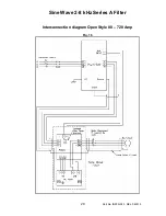
*See fig. 16 for customer wire connections.  

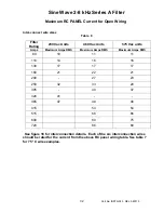
*Size interconnecting wire to carry current shown on table 8. 

Summary of Contents for Sine Wave Filter

Page 1: ...2008 MTE Corporation PART NO INSTR 020 REL 080310 M T E C o r p o r a t i o n Sine Wave Filter Series A 200 600 VAC USER MANUAL...

Page 2: ...d power conversion applications The suitability of this filter for a specific application must therefore be determined by the customer In no event will MTE Corporation assume responsibility or liabili...

Page 3: ......
Page 4: ...TA 8 200 230 VOLTS 8 380 480 VOLTS 9 550 600 VOLTS 10 6 INSTALLATION INSTRUCTIONS 11 OPEN PANEL CUSTOMER CONNECTIONS 12 VERTICAL MOUNTING OF OPEN REACTOR RC PANEL 19 350HP MCC USING OPTIONAL BAY FOR S...

Page 5: ...the indicated voltage falls below the maximum value of the next lower scale used WARNING The opening of the branch circuit protective device may be an indication that a fault current has been interrup...

Page 6: ...TE Sine Wave Filter has been subjected to demanding factory tests before shipment Carefully inspect the shipping container for damage that may have occurred in transit Then unpack the filter and caref...

Page 7: ...ation SW A X Y _ _ _ _ X YY Sine Wave filter Series Version A X Options X denotes Non standard Configurations 01 NC Overtemp Mechanical Configuration P Panel Mount G General Purpose NEMA 1 or 2 W NEMA...

Page 8: ...93 6 149 94 88 93 98 14 95 7 96 7 191 98 32 120 9 95 9 125 98 26 128 98 31 155 12 96 1 206 98 35 162 98 54 177 17 96 1 279 98 90 151 98 73 219 22 97 3 362 98 72 229 98 86 253 27 99 01 216 98 92 295 30...

Page 9: ...600 VAC 50 50 60 60 Hz Three Phase Note Short Circuit rating not required under Exception No 1 of UL508A SB4 2 1 effective 4 25 06 Current Rating Continuous current rating 100 RMS Intermittent curren...

Page 10: ...Sine Wave 2 8 kHz Series A Filter 6 Part No INSTR 020 REL 080310 Typical Performance Data Fig 1 Raw drive output voltage Fig 2 Output voltage after sine wave filter...

Page 11: ...verter Frequency De rating Chart 2 Sine Wave Filter Current Derating for Drive output Frequency 0 6 0 65 0 7 0 75 0 8 0 85 0 9 0 95 1 1 05 50 60 70 80 90 100 Output Drive Frequency Hertz Current Derat...

Page 12: ...17A 104 10 22 SWAP0022A 32 3 SWAGB0022A 57 9 SWAWB0022A 133 11 30 SWAP0030A 38 4 SWAGB0030A 60 9 SWAWB0030A 136 11 45 SWAP0045A 47 4 SWAGB0045A 69 9 SWAWB0045A 145 11 55 SWAP0055A 55 4 SWAGB0055A 77 9...

Page 13: ...SWAGB0045D 137 9 SWAWB0045D 150 11 55 SWAP0055D 67 4 SWAGB0055D 147 9 SWAWB0055D 160 11 65 SWAP0065D 77 5 SWAGB0065D 157 9 SWAWB0065D 170 11 80 SWAP0080D 86 5 SWAGC0080D 246 12 SWAWC0080D 270 12 110...

Page 14: ...151 11 45 SWAP0045E 63 4 SWAGB0045E 143 9 SWAWB0045E 156 11 55 SWAP0055E 75 5 SWAGB0055E 155 9 SWAWB0055E 168 11 65 SWAP0065E 86 5 SWAGB0065E 166 9 SWAWB0065E 179 11 80 SWAP0080E 117 A1 B SWAGC0080E 2...

Page 15: ...ed Keep the capacitors away from reactor and resistor heat flow Avoid locations where the filter would be subjected to excessive vibrations Figures 3 5 contain open panel outline drawings for the vari...

Page 16: ...Sine Wave 2 8 kHz Series A Filter 12 Part No INSTR 020 REL 080310 Open Panel Customer connections Open Panel 3 30 Amps 200 230 VAC 9 17 AMPS 380 480 VAC 9 12 AMPS 550 600 VAC Fig 3 17 Amp Shown...

Page 17: ...Sine Wave 2 8 kHz Series A Filter 13 Part No INSTR 020 REL 080310 Open Panel 45 60 AMPS 200 230 VAC 22 55 AMPS 440 480 VAC 17 45 AMPS 550 600 VAC Fig 4 45 Amp shown...

Page 18: ...Sine Wave 2 8 kHz Series A Filter 14 Part No INSTR 020 REL 080310 Open Panel 65 80 AMPS 440 480 VAC 55 65 AMPS 550 600 VAC Fig 5 80 Amp Shown...

Page 19: ...C panel should be located in the lowest temperature regions of the enclosure generally toward the bottom An example of an MCC application is shown in Figure 7 Table 4 FIG A DIMENSIONS Inches Figure A...

Page 20: ...Sine Wave 2 8 kHz Series A Filter 16 Part No INSTR 020 REL 080310 RC Panel 85 160 AMPS 200 230 VAC 110 160 AMPS 380 480 VAC 80 250 AMPS 550 600 VAC Fig B...

Page 21: ...Sine Wave 2 8 kHz Series A Filter 17 Part No INSTR 020 REL 080310 RC Panel 200 320 AMPS 200 230 VAC 200 515 AMPS 380 480 VAC 305 365 515 AMPS 550 600 VAC Fig C...

Page 22: ...Sine Wave 2 8 kHz Series A Filter 18 Part No INSTR 020 REL 080310 RC Panel 600 720 AMPS 440 480 VAC 415 600 720 AMPS 550 600 VAC Fig D...

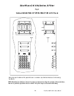
Page 23: ...OF OPEN REACTOR RC Panel 600 amp open reactor RC panel shown in customer provided enclosure and mounting hardware NOTE Maintain orientation as shown for proper component cooling Do not place RC panel...

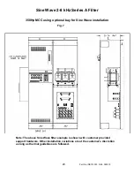
Page 24: ...0310 350Hp MCC using optional bay for Sine Wave installation Fig 7 Note The above Sine Wave filter example is shown with customer provided support hardware Other installation variations are at the cus...

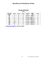
Page 25: ...GA 13 13 13 Cab 13V NEMA 1 8 GB 17 24 18 Cab 17V NEMA 1 9 GC 27 47 25 Cab 26C NEMA 1 2 12 GD 31 72 31 Cab 30C NEMA 1 2 13 GE 43 72 25 Cab 42C NEMA 1 2 14 WA 12 5 24 18 Cab 12C NEMA 3R 10 WB 17 5 31 21...

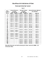
Page 26: ...B 17C CAB 17V CAB 17C 30 CAB 17V CAB 17C 35 CAB 17V CAB 17C CAB 17V CAB 17C CAB 17V CAB 17C 45 CAB 17V CAB 17C CAB 17V CAB 17C CAB 17V CAB 17C 55 CAB 17V CAB 17C CAB 17V CAB 17C CAB 26C CAB 26C 65 CAB...

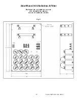
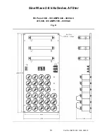
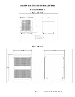
Page 27: ...Sine Wave 2 8 kHz Series A Filter 23 Part No INSTR 020 REL 080310 Enclosed NEMA 1 Fig 8 Cab 13V Fig 9 Cab 17V...

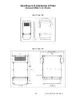
Page 28: ...Sine Wave 2 8 kHz Series A Filter 24 Part No INSTR 020 REL 080310 Enclosed NEMA 1 2 3R units Fig 10 Cab 12C Fig 11 Cab 17C...

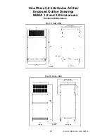
Page 29: ...Sine Wave 2 8 kHz Series A Filter 25 Part No INSTR 020 REL 080310 Enclosed Outline Drawings NEMA 1 2 and 3R Enclosures Enclosure Dimensions Fig 12 Cab 26C Fig 13 Cab 30C...

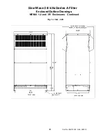
Page 30: ...Sine Wave 2 8 kHz Series A Filter 26 Part No INSTR 020 REL 080310 Enclosed Outline Drawings NEMA 1 2 and 3R Enclosures Continued Fig 14 Cab 42C...

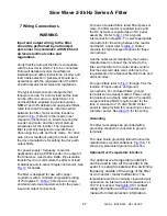
Page 31: ...rees C Table 7 lists the wire range and terminal torque requirements for the power input and output connections For panel mounted filters rated 80 amperes or more the filter reactor is supplied loose...

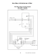
Page 32: ...Sine Wave 2 8 kHz Series A Filter 28 Part No INSTR 020 REL 080310 Sine Wave Interconnection diagram Open Style 2 80 Amps Enclosed 2 720 Amps Fig 15...

Page 33: ...Sine Wave 2 8 kHz Series A Filter 29 Part No INSTR 020 REL 080310 Interconnection diagram Open Style 80 720 Amp Fig 16...

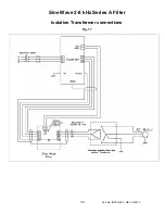
Page 34: ...Sine Wave 2 8 kHz Series A Filter 30 Part No INSTR 020 REL 080310 Isolation Transformer connections Fig 17...

Page 35: ...12 22 5 16 N R 17 22 5 16 N R 22 22 5 16 N R 27 22 5 16 N R 35 22 5 16 N R 45 18 4 20 N R 55 18 4 20 N R 65 6 4 2 0 50 N R 80 6 4 2 0 50 12 110 3 0 75C 250 12 130 4 0 75C 250 12 160 3 0 90C 250 8 200...

Page 36: ...units Amps Maximum Amps RMS Maximum Amps RMS Maximum Amps RMS 80 10 11 11 110 14 16 16 130 17 17 17 160 21 22 21 200 27 23 250 32 33 29 305 40 37 320 41 365 47 49 46 415 54 54 515 66 66 600 80 75 720...

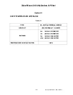
Page 37: ...NSTR 020 REL 080310 Option 01 OVER TEMPERATURE INTERLOCK Table 9 TYPE BI METAL THERMAL SWITCH CONTACT NC NORMALLY CLOSED RATINGS 6A 120 VAC RESISTIVE 3A 240 VAC RESISTIVE 5A 120 VAC INDUCTIVE 2 5A 240...

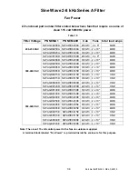
Page 38: ...30C2 3 2 x 10 0 96 SWAGD0415D SWAWD0415D 30C2 3 4 x 10 1 92 SWAGD0515D SWAWD0515D 30C2 3 4 x 10 1 92 SWAGE0600D SWAWE0600D 42C2 3 4 x 10 1 92 380 480 VAC SWAGE0720D SWAWE0720D 42C2 3 4 x 10 1 92 SWAG...

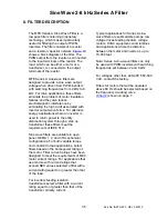
Page 39: ...ough a step up transformer these filters meet the requirements of IEEE 519 Sine wave filters are available in open panel NEMA 1 2 and 3R mechanical configurations For both variable torque and constant...

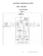
Page 40: ...Sine Wave 2 8 kHz Series A Filter 36 Part No INSTR 020 REL 080310 200 V 600 VAC BLOCK DIAGRAM FIGURE 18...

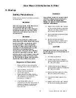
Page 41: ...e connected to ground Power wiring to the utility inverter filter and motor is in accordance with the installation and connection instructions in Chapter 5 3 Check that moisture has not condensed on t...

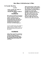
Page 42: ...ure 17 and interconnection diagrams are shown in figures 15 and 16 A list of potential problems and solutions are listed below WARNING High voltage is used in the operation of this filter Use Extreme...

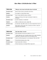
Page 43: ...ger filter Possible cause Inverter fault Large filter causes over current fault by filter cap load Solution Select filter to match motor FLA increase size of drive to allow for long lead cable applica...

Page 44: ...2 3 Sine Wave Filter Series A 200 600 VAC User Manual INSTR 020 Revision Date Revision History 10 12 05 New document written by Wayne Walcott 080310 03 09 08 By WRW Updated per ECN 5695 updated open p...

Reviews: