background image

1) Switch:

Consists of the roadbed, rails, points, frog, screw terminals, operating 

circuitry and mechanisms.

2) Screw Terminal Cover:

Plastic cover that attaches to the roadbed and conceals the screw terminals.

3) Jumper:

Removable metal connector between 4th and 5th screw terminals.  The 

Jumper acts as a switch between track and auxiliary power.

4) Switch Block:

Consists of housing, solenoid coils and lantern.  The Switch Block attaches 

to either rectangular port at the converging end of the Switch.  The Switch 

Block may be attached to either side of the switch.

(See Figure 4)

5) Switch Block Cover:

Plastic cover that attaches to and conceals the unused Switch Block port.

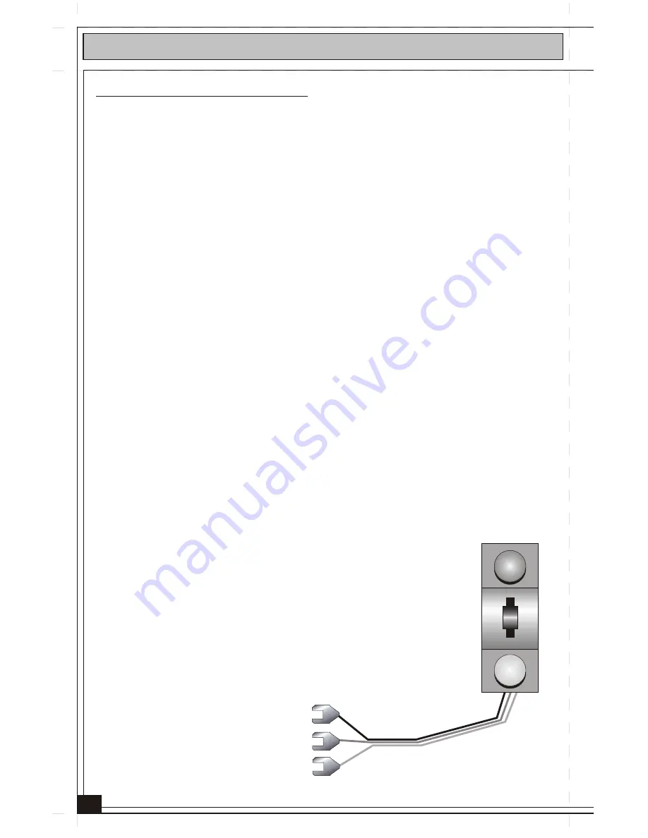
6) Remote Switch:

Separate manual switch with momentary action.  The Remote Switch can 

operate your switch from anywhere on your layout.

RealTrax O-31 Switch Components:

®

RealTrax  O-31 Switch Operating Instructions:

4

6

Summary of Contents for RealTrax O-3

Page 1: ...umbia MD 21046 1532 O 31 S W I T C H MTH RealTrax switches add flexibility and reliability to your O Gauge RealTrax layout Designed to provide years of trouble free smooth operation RealTrax switches are the perfect additions to expand your RailKing empire ...

Page 2: ...ple Switch Operation Through One Remote Switch 10 Track Power Opposite Throws Auxiliary Powered Switch Operating Instructions 10 Multiple Switch Operation Through Separate Remote Switches 11 Multiple Switch Operation Through One Remote Switch 11 Auxiliary Power Identical Throws Multiple Switch Operation Through One Remote Switch 12 Auxiliary Power Opposite Throws RealTrax O 31 Switches In Tubular ...

Page 3: ...nts always will be in the correct position If you change directions with a RealTrax Switch you will not have to worry about derailments or electrical short circuits The RealTrax Switch can be wired for operation via track power or auxiliary power Also you will be able to operate several RealTrax Switches together by following the appropriate illustrated diagram s in this manual It can be installed...

Page 4: ...r 4 Switch Block Consists of housing solenoid coils and lantern The Switch Block attaches to either rectangular port at the converging end of the Switch The Switch Block may be attached to either side of the switch See Figure 4 5 Switch Block Cover Plastic cover that attaches to and conceals the unused Switch Block port 6 Remote Switch Separate manual switch with momentary action The Remote Switch...

Page 5: ...5 1 2 3 4 5 Figure 1a ...

Page 6: ...at causes the points rails that shift positions to align with the curved direction of travel The Curved AC Screw Terminal may be connected to either the RED wire of the Remote Switch or an external AC power source ACG Common Screw Terminal This Screw Terminal is the electrical ground connection for all power and Remote Switch inputs Auxiliary Power AC In Screw Terminal This Screw Terminal is the i...

Page 7: ...INAL The JUMPER between the fourth and fifth SCREW TERMINALS remains in place Basic Switch Operation Now that your RealTrax Switch is wired you will be able to operate it via any of the following methods Figure 3 1 2 3 3 Remote Switch operation 1 Push the remote switch lever toward the green light for straight operation Push the remote switch lever toward the red light for curved operation Manual ...

Page 8: ...ing it firmly into the roadbed Install the Switch Block Cover into the other side 3 You will have to change the position of the Switch Block Lantern so that the Green lenses align to the straight direction and the red lenses align to the curved direction a Hold the Switch Block Lantern between your thumb and forefinger Gently pull the Lantern out of its socket b Rotate the Lantern 90 Degrees one q...

Page 9: ...screw terminal of the Primary Switch to the STRAIGHT AC screw terminal of the Secondary Switch Connect the CURVED AC screw terminal of the Primary Switch to the CURVED AC screw terminal of the Secondary Switch Connect the ACG Common screw terminal of the Primary Switch to the ACG Common screw terminal of the Secondary Switch RealTrax O 31 Switch Multiple Switch Operation 9 Figure 6 Making Multiple...

Page 10: ...ew terminal of the Primary Switch to the ACG Common screw terminal of the Secondary Switch Remove Jumper between Track AC Out terminal and Aux Power AC In terminals Save the jumper for future use Connect Remote Switch as shown in Figure 2 Connect Auxiliary Power AC to Auxiliary Power AC In screw terminal Connect Auxiliary Power ACG Common to ACG Common screw terminal Auxiliary Powered Switch Opera...

Page 11: ...y Power AC to all auxiliary powered switch Aux Power In AC screw terminals either in series from one Switch AC terminal to the next or in parallel each Switch AC terminal is wired directly to the auxiliary power source Remove Jumpers from all auxiliary powered switches Connect Remote Switch to primary switch as shown in Figure 2 Connect Auxiliary Power AC to Auxiliary Power AC In screw terminal of...

Page 12: ...witch Connect Auxiliary Power ACG Common to ACG Common screw terminal of primary switch Connect the STRAIGHT AC screw terminal of the Primary Switch to the CURVED AC screw terminal of the Secondary Switch Connect the CURVED AC screw terminal of the Primary Switch to the STRAIGHT AC screw terminal of the Secondary Switch Connect the ACG Common screw terminal of the Primary Switch to the ACG Common ...

Page 13: ...apter Track section 5 long to each arm of the RealTrax O 31 Switch The steel pins of your tubular track will insert into the tubular rail portion of the RealTrax Adapter Track Figure 13 13 RealTrax Adapter Track Section 40 1011 RealTrax Adapter Track Section 40 1011 RealTrax Adapter Track Section 40 1011 RealTrax O 31 Switches In Tubular Rail Layouts ...

Page 14: ... Multiple Train Operation Powered Unpowered Siding X X X X X X X X Figure 14 Layout Instructions Note this layout requires a Single Pole Double Throw switch minimum 3A rating available at a hardware or electrical store 1 To assemble a RiteTrax layout for Powered Unpowered Siding Operation you will have to isolate the outside rail of the A Line and the outside rail of the B Line To do this bend bac...

Page 15: ...e Track AC Out Screw terminal and the Auxiliary AC Power In Screw Terminal is installed If using Aux Power check connection If using auxiliary power to operate the switch check that the jumper between the Track AC Out Screw Terminal and the Auxiliary AC Power In Screw Terminal is removed If using track power check connection Check that the operating voltage track or auxiliary is at least 10V If op...

Page 16: ...rranty does not cover items that have been abused or damaged by careless handling Transportation costs incurred by the customer are not covered under this warranty This warranty gives you specific legal rights and you may have other rights which vary from state to state MTH and RailKing are registered trademarks of MTH Electric Trains HOW TO GET SERVICE UNDER THE TERMS OF THE LIMITED ONE YEAR WARR...

Reviews: