13
INM9312-FB-ST-SS-1
Oct 2008
13
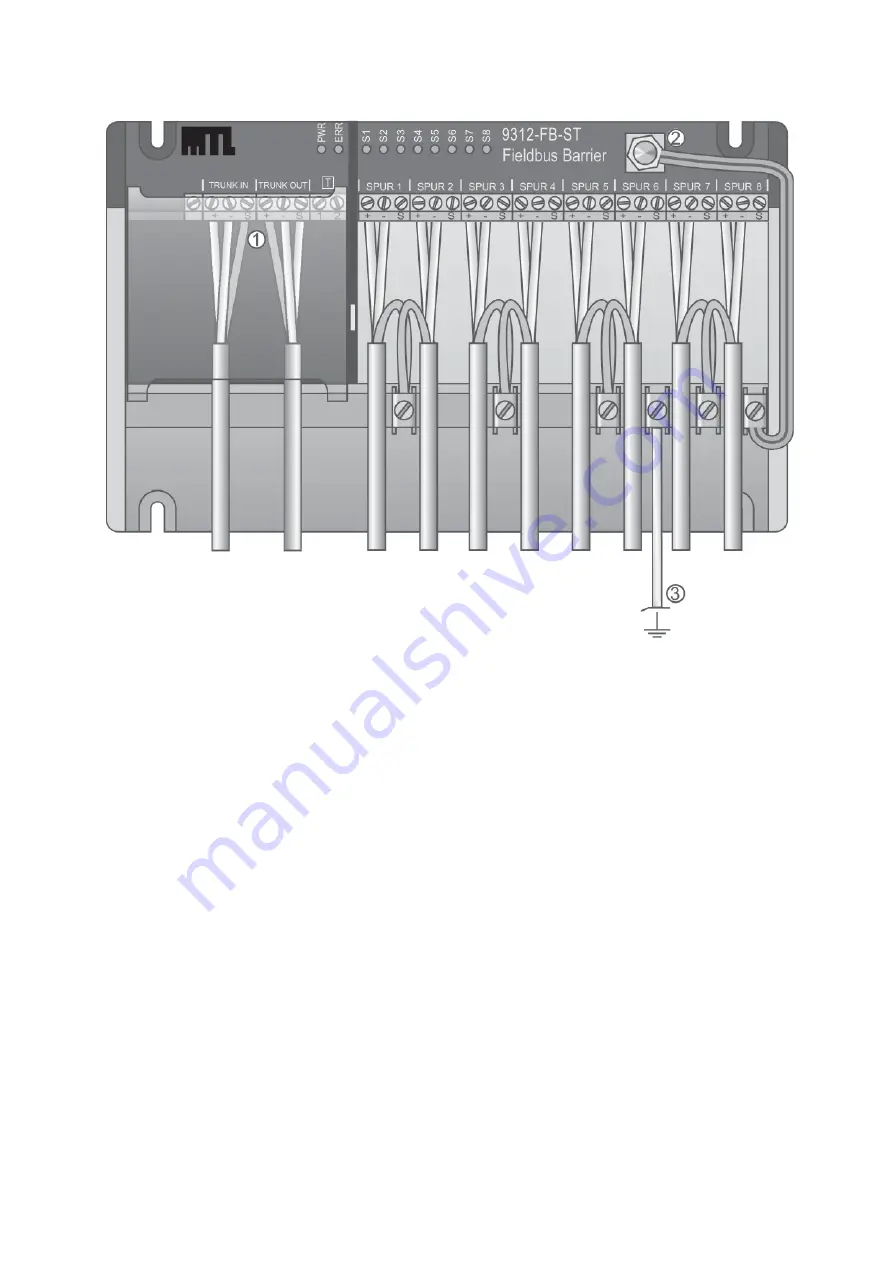
Option 2 - Local grounding of spur cable shields
If plant or local regulations require that the spur cable shields be grounded at the Fieldbus Barrier, then
the arrangement shown in Figure 11 may be adopted.
With this arrangement, the spur cable shields are connected to local ground via the cable shield busbar.
The trunk cable shields are connected to ground via 4,7
μ
F capacitors that are internally connected
between the ‘S’ terminals of the trunk terminal block and the grounding stud (2).
The connection between the cable shield busbar and local ground (3) can be omitted if the Fieldbus
Barrier is installed into a steel enclosure using mounting screws, as there is electrical continuity between
the grounding stud (2) and the enclosure body.
Capacitive grounding of the spur cables can also be configured by connnecting the spur cable shield to
the ‘S’ terminals of the spur terminal blocks.
Figure 11: Spur cable shields to earth busbar


