5
INM9312-FB-ST-SS-1
Oct 2008
5
4 FUNCTIONAL
DESCRIPTION
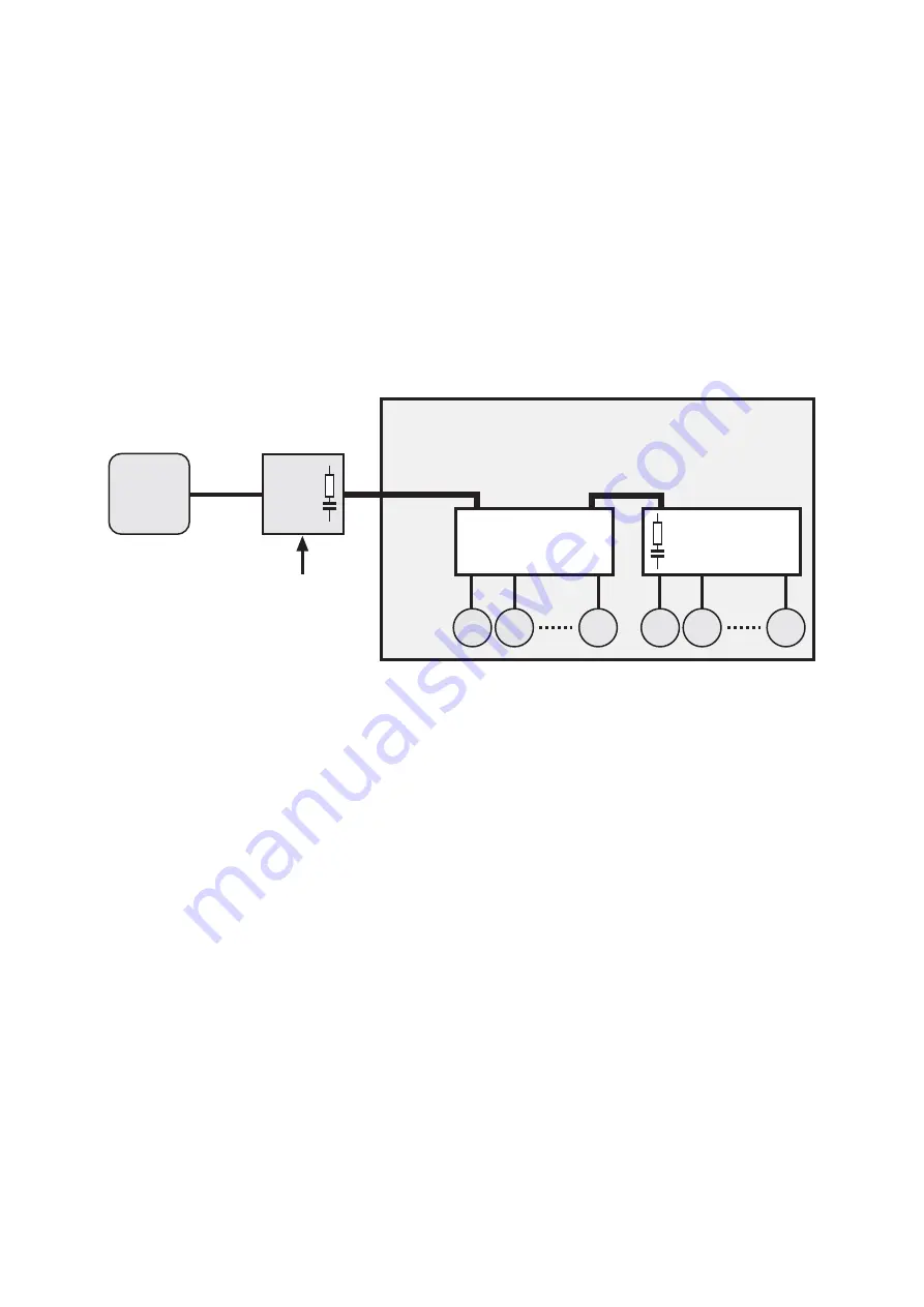
Each 9312-FB-ST-SS-SP Fieldbus Barrier is used for connecting up to eight, intrinsically safe field devices
to a non-intrinsically safe trunk; providing galvanic isolation between trunk and spurs. Up to four 9312-
FB-ST-SS-SP Fieldbus Barriers may be connected in a filedbus segment, thereby providing up to 32
spurs.
The Fieldbus Barrier functions at the physical level only; it is independent of the protocol used. It can
therefore be used for every fieldbus that is compliant with IEC 61158-2. At this time, these include the
F
OUNDATION
fieldbus H1 and the Profibus PA.
A fieldbus terminator is built in and can be implemented via a jumper link.
Cable shields can either be capacitively or directly earthed.
The trunk voltage connecting to the Fieldbus Barrier is monitored for undervoltage (< 16V) and indicated
by an LED. Other LEDs indicate the status of the spurs.
4.1 Power
management
As soon as the voltage on the trunk exceeds 16V, the spurs are activated in turn to avoid a high start-
up current. In the event of a short-circuit, the spur in question is de-activated until the short-circuit is
removed.
If several spurs are in a short-circuit condition, the trunk is loaded with a maximum of only
one
short-
circuit current. This minimises the current consumption of the trunk and the power loss of the Fieldbus
Barrier under all operating conditions.
The total current available across all eight spurs is 160mA. An average current of 20mA is therefore
available to each spur, which is adequate in practice as most fieldbus instruments require less than 20mA
to operate. Individual spurs can supply a continuous current of 40mA, provided the total current budget
of 160mA is not exceeded. This allows a hand-held test device to be connected in parallel with an
instrument, for example, or the connection of an instrument which requires a higher operating current.
On power-up, the spurs are energised in sequence under the control of in internal microprocessor.
Approximately 50mA is available momentarily at each spur to accommodate inrush current.
The 931x-FB Fieldbus Barrier Calculator Tool models the behaviour of the 9312-FB-ST-SS-SP and can be
used to design fieldbus segments; taking into account the individual spur currents, trunk cable length and
power supply characteristics. A single spur short-circuit can also be assumed per segment. Warnings are
displayed if any design parameters are exceeded.
Host
Fieldbus
power
supply
Trunk Ex e
Field
devices
Power
Spurs Ex i
Terminator
Fieldbus Barrier
Fieldbus Barrier
Zones 1, 2,
1
2
8
1
2
8
Figure 3: Functional diagram


