background image

14

INM4500-2

Mar 2009

MTL4510B modes

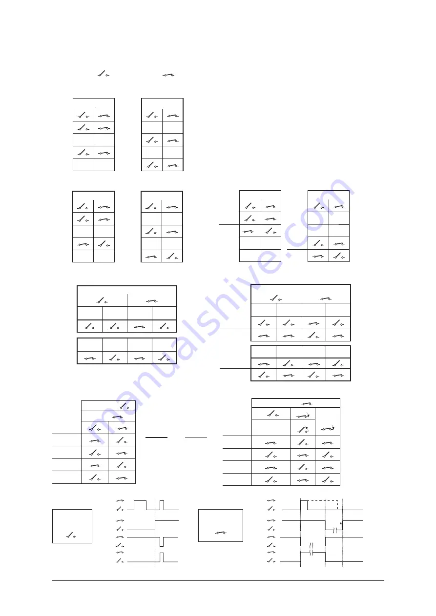
The following logic and timing diagrams are provided to assist the user in understanding the behaviour of the MTL4510B module 
when a specific 

mode

 is chosen.

The open switch (

) and closed switch (

) symbols are used to represent both the input conditions of Ch A, Ch B, Ch C or 

Ch D and then the output conditions of o/p 1, 2, 3 or 4.

How to use these mode tables - examples

The logic tables (right) for Mode 1 represent Ch A controlling outputs 
1 & 3, while Ch C controls outputs 2 & 4.

Output 1 & 3 are shown following input Ch A (open or closed) while 
Outputs 2 & 4 follow input Ch C.

Mode 2 however shows o/p 3 and 4 being in antiphase to their 
inputs.

Mode 1

i/p - Ch A

i/p - Ch C

o/p 1

-

-

-

-

o/p 2

o/p 3

-

-

-

-

o/p 4

Mode 2 


i/p - Ch A


i/p - Ch C

o/p 1

-

-

-

-

o/p 2

o/p 3

-

-

-

-

o/p 4

Mode 3 


i/p - Ch A


i/p - Ch C

o/p 1

-

-

o/p 2

-

-

-

-

o/p 3

-

-

o/p 4

i/p - Ch A

No

fault

Line

fault 

No

fault

Line

fault 


o/p 1

Mode 4 

No

fault

Line

fault 

No

fault

Line

fault 


o/p 3

i/p - Ch A

No

fault

Line

fault 

No

fault

Line

fault 

o/p 1

o/p 2

Mode 5 

No

fault

Line

fault 

No

fault

Line

fault 

LFD o/p 3


LFD o/p 4

i/p Ch C

Non-latching


i/p Ch B

Enable  

i/p Ch A


o/p 1

o/p 2

o/p 3

o/p 4

Mode 6 

i/p Ch C

Latching


i/p Ch A


Start

Reset

i/p Ch B

No effect

Stop 

o/p 1

o/p 2

o/p 3

o/p 4

A

Start

B

Stop

i/p Ch A

i/p Ch B

o/p 2&4

o/p 1&3

B

Reset

*

* i/p Ch A can be open or closed when i/p Ch B opens to stop latch

o/p 2&4

o/p 1&3

(enable)

i/p Ch A

i/p Ch B

OR

Non-latching

Ch C open

Latching

Ch C closed

Summary of Contents for MTL4500 Series

Page 1: ...MTL合作伙伴 滨州新大新机电科技有限公司 Instruction Manual INM4500 MTL4500 Series isolating interface units ...

Page 2: ...ii INM4500 2 Mar 2009 ...

Page 3: ...detector interface 18 6 1 6 MTL4516 Switch Proximity detector interface 19 6 1 7 MTL4516C Switch Proximity detector interface 20 6 1 8 MTL4517 Switch Proximity detector interface 21 6 2 Digital Output modules 22 6 2 1 MTL4521 Solenoid Alarm driver 22 6 2 3 MTL4523 MTL4523R Solenoid Alarm driver 23 6 2 4 MTL4523L Solenoid Alarm driver 24 6 2 5 MTL4524 Solenoid Alarm driver 25 6 2 6 MTL4524S Solenoi...

Page 4: ...s then MTL document INA4500 must be consulted before installation CERTIFICATION DATA The MTL web site http www mtl inst com contains product documentation regarding intrinsic safety certification for many locations around the world Consult this data for information relevant to your local certifying authority REPAIR These products MUST NOT be repaired Faulty or damaged products must be replaced wit...

Page 5: ...es which carry safe area signals and power supplies Hazardous area circuits are connected to the terminals on the modules Backplanes can be integrated into a user s process system architecture or mounted in separate enclosures 2 MTL4500 SERIES DESCRIPTION Each module has a multi pin connector in its base that plugs into a matching connector on the backplane This connector carries all appropriate s...

Page 6: ...STALLATION PRECAUTIONS 3 1 General Please read this section before beginning to install backplanes enclosures modules etc 3 2 Precautions Make sure that all installation work is carried out in accordance with all relevant local standards codes of practice and site regulations Check that the hazardous area equipment complies with the descriptive system document If in doubt refer to the certificate ...

Page 7: ...l T or G 19 inch rack Earth rail kit Tagging strip kit Spare fuse pack CPS04 4 Screw clamp SMS01 DMK01 FUS08 CPS08 8 Screw clamp SMS01 DMK01 ERK08 TSK08 FUS08 CPS16 16 Screw clamp SMS01 DMK01 ERK16 TSK16 FUS16 CPS24 24 Screw clamp SMS01 DMK01 HMP24 TSK24 FUS24 Table 4 1 Backplanes mounting kits and accessories Locking washer 2 Plain washer 3 M4 x 20mm screw 1 MTL4500 backplane Mounting hole A Reta...

Page 8: ...fitted on the DIN rails immediately below the lowest backplane fixing This will avoid the chance of backplane slippage down the DIN rail 4 1 3 19 inch rack mounting CPS24 backplanes with HMP24 mounting plate See Figure 4 4 Place an unloaded backplane onto the HMP24 mounting plate Attach the backplane to the mounting plate at centres A with the eight M4 x 12mm screws provided Attach the assembly to...

Page 9: ...tic retaining tie 7 with two plastic rivets 8 Figure 4 6 Clip the tag strip holder 6 onto the mounting posts 1 by pushing it downwards Figure 4 7 If required swivel the tagging strip vertically Figure 4 7 a b c d e f g Colour Module no Function White MTL451x Digital Inputs Red MTL452x Digital Outputs Blue MTL4541 MTL4544 Analogue Inputs Green MTL4546 MTL4549 Analogue Outputs Orange MTL4575 Tempera...

Page 10: ...with a 6 way split level terminal block for safe area signals The six terminals reproduce the module terminals numbered 7 to 12 as shown in Figure 4 9 Make the appropriate connections to the terminal block in accordance with the pin assignment numbers reproduced in Figure 4 9 Wire entry for each terminal is from the side of the block The maximum permissible wire gauge is 2 5mm2 14 AWG 4 4 2 Safe a...

Page 11: ...e backplane will light if the two independent supplies are operational The diodes between the two ensures that the highest voltage supply is the one in use at any given moment and providing automatic switchover of supplies if one source fails Connect the power supply cables to the connector according to the pin assignments shown in Figure 4 12 The maximum permissible wire size is 2 5mm2 14 AWG Plu...

Page 12: ...etection LFD The following information applies to all DI modules with LFD except for the MTL4501 SR When using the LFD facility with a contact input resistors must be used Fit 500Ω to 1kΩ in series with switch and 20kΩ to 25kΩ in parallel with switch For hazardous area inputs conforming to EN 60947 5 6 2001 NAMUR a line fault is judged by the following rules Open circuit condition if hazardous are...

Page 13: ...an often be successfully used if the crimping is good 5 2 3 Finishing Wire up individual isolators in accordance with wiring schedules Segregate hazardous and safe area wiring into separate trunking or looms wherever possible to avoid errors and maintain a tidy installation Use an MTL4599 dummy isolator to provide termination and earthing for unused cores from the hazardous area 5 2 4 Module mount...

Page 14: ...NING When disconnecting units for maintenance purposes take care to segregate hazardous and safe area cables Short circuit hazardous area cable cores to an IS earth or insulate and secure the ends Insulate and secure safe area cables If testing a unit in situ note that the test equipment used MUST be intrinsically safe The rest of this section is divided into sub sections based upon the type of mo...

Page 15: ...ection The MTL4501 SR enables a fail safe switch proximity detector located in the hazardous area to control an isolated fail safe electronic output The MTL4501 SR unit provides line fault detection alarm contacts The MTL4501 SR is designed for use with approved fail safe sensors 1 2 3 4 5 6 7 8 9 10 1112 13 14 Fail safe ouput 10kW 1k4W LFD Resistors must always be fitted for switch inputs Vs Vs 2...

Page 16: ...TL4510B has more varied modes that can for example enable one input to affect multiple outputs or create latched outputs etc Tables 6 1 and 6 2 show details of the modes available and the switch settings required to obtain them Figure 6 2 LED indicators for MTL4510 MTL4510B Terminal Function 1 Input channel A 2 Input channel AB common 3 Input channel B 4 Input channel C 5 Input channel CD common 6...

Page 17: ...changeover outputs OFF ON ON OFF 6 1 ch with start stop latch MTL2210B ON ON ON OFF 7 4 ch switch input see MTL4510 mode 7 MTL4510 OFF OFF OFF ON 8 4 ch switch input see MTL4510 mode 8 MTL4510 ON OFF OFF ON 9 2 ch with line fault output MTL4017 OFF ON OFF ON 10 As mode 9 with LFD changeover ON ON OFF ON 11 As mode 10 with channel phase reversed OFF OFF ON ON 12 3 ch with normally open LFD output O...

Page 18: ... shows o p 3 and 4 being in antiphase to their inputs Mode 1 i p Ch A i p Ch C o p 1 o p 2 o p 3 o p 4 Mode 2 i p Ch A i p Ch C o p 1 o p 2 o p 3 o p 4 Mode 3 i p Ch A i p Ch C o p 1 o p 2 o p 3 o p 4 i p Ch A No fault Line fault No fault Line fault o p 1 Mode 4 No fault Line fault No fault Line fault o p 3 i p Ch A No fault Line fault No fault Line fault o p 1 o p 2 Mode 5 No fault Line fault No ...

Page 19: ...lt No fault Line fault o p 1 i p Ch B No fault Line fault No fault Line fault o p 2 i p Ch C No fault Line fault No fault Line fault o p 3 Mode 13 As mode 12 but with LFD o p 4 reversed No fault Line fault No fault Line fault LFD o p 4 Mode 14 This mode provides a two channel pulse stretcher for inputs A and C Outputs 1 and 2 respond to Ch A while 3 and 4 respond to Ch C Input B or D being open or...

Page 20: ...le and output is provided by the changeover relay contacts See Section 5 1 1 on page 8 for LFD and PR switch details Channel 1 only switch settings apply For switch sensor inputs with LFD selected make sure resistors 22kΩ and 680Ω are fitted Note Signal plug HAZ1 3 is required for access to the earth leakage detector function PWR STS LFD MTL4511 Figure 6 3 LED indicators for MTL4511 Hazardous area...

Page 21: ...ion 5 1 1 on page 8 for LFD and PR switch details Channel 1 2 switch settings apply For switch sensor inputs with LFD selected make sure resistors 22kΩ and 680Ω are fitted Note Signal plug HAZ1 3 is required for access to the earth leakage detector function PWR STS LFD STS LFD MTL4513 CH2 CH1 Figure 6 4 LED indicators for MTL4513 Terminal Function 1 Input ve Ch 1 2 Input ve Ch 1 3 To earth leakage...

Page 22: ...ction 5 1 1 on page 8 for LFD and PR switch details Channel 1 only switch settings apply For switch sensor inputs with LFD selected make sure resistors 22kΩ and 680Ω are fitted Note Signal plug HAZ1 3 is required for access to the earth leakage detector function Figure 6 5 LED indicators for MTL4514 Safe area Hazardous area 1 2 3 4 5 6 7 8 9 10 1112 13 14 7 8 9 10 1112 13 14 LFD LFD Vs Vs 20 35V d...

Page 23: ...y the changeover relay contacts See Section 5 1 1 on page 8 for LFD and PR switch details Channel 1 2 switch settings apply For switch sensor inputs with LFD selected make sure resistors 22kΩ and 680Ω are fitted Note Signal plug HAZ1 3 is required for access to the earth leakage detector function Hazardous area Safe area 1 2 3 4 5 6 7 8 9 10 1112 13 14 Vs Vs 20 35V dc Ch 1 Ch 1 Ch 2 Ch 2 22kW 680W...

Page 24: ...5 1 1 on page 8 for LFD and PR switch details Channel 1 2 switch settings apply For switch sensor inputs with LFD selected make sure resistors 22kΩ and 680Ω are fitted Note Signal plug HAZ1 3 is required for access to the earth leakage detector function Figure 6 7 LED indicators for MTL4516C Hazardous area Safe area 1 2 3 4 5 6 7 8 9 10 1112 13 14 Vs Vs 20 35V dc Ch 1 Ch 1 Ch 2 Ch 2 22kW 680W 22kW...

Page 25: ...Channel 1 2 switch settings apply For switch sensor inputs with LFD selected make sure resistors 22kΩ and 680Ω are fitted Note Signal plug HAZ1 3 is required for access to the earth leakage detector function Figure 6 8 LED indicators for MTL4517 Safe area Hazardous area 1 2 3 4 5 6 7 8 9 10 1112 13 14 7 8 9 10 1112 13 14 LFD Vs Vs 20 35V dc 2 1 Ch 1 Ch 2 22kW 680W 22kW 680W To MTL earth leakage de...

Page 26: ...ice located in the hazardous area IIC gas group to be controlled from the safe area The MTL4521 can drive up to 48mA into a certified intrinsically safe low power load as well as non energy storing simple apparatus such as an LED Note Signal plug HAZ1 3 is required for access to the earth leakage detector function Figure 6 9 LED indicators for MTL4521 STS MTL4521 Hazardous area Safe area 1 2 3 4 5...

Page 27: ...ine is open or short circuited Earth fault detection can be provided by connecting an MTL4220 earth leakage detector to terminal 3 Note Signal plug HAZ1 3 is required for access to the earth leakage detector function Figure 6 11 LED indicators for MTL4523 and MTL4523R Hazardous area 1 2 3 4 5 6 7 8 9 10 1112 13 14 Solenoid alarm or other IS device LFD To MTL earth leakage detector MTL4523R phase r...

Page 28: ...h which energises if a field line is open or short circuited Earth fault detection can be provided by connecting an MTL4220 earth leakage detector to terminal 3 Note Signal plug HAZ1 3 is required for access to the earth leakage detector function Hazardous area Safe area 1 2 3 4 5 6 7 8 9 10 1112 13 14 LFD Solenoid alarm or other IS device To MTL earth leakage detector Vs Vs 20 35V dc Terminal Fun...

Page 29: ... By connecting a second safe area switch or logic signal the output can be disabled to permit for example a safety system to override a control signal Note Signal plug HAZ1 3 is required for access to the earth leakage detector function Figure 6 13 LED indicators for MTL4524 PWR STS MTL4524 Hazardous area Safe area 1 2 3 4 5 6 7 8 9 10 1112 13 14 Vs Vs 20 35V dc Control Override Solenoid alarm or ...

Page 30: ...ratus By connecting a second safe area switch or logic signal the output can be disabled to permit for example a safety system to override a control signal Note Signal plug HAZ1 3 is required for access to the earth leakage detector function Hazardous area Safe area 1 2 3 4 5 6 7 8 9 10 1112 13 14 Vs Vs 20 35V dc Control Override Solenoid alarm or other IS device 24V To MTL earth leakage detector ...

Page 31: ... By connecting a second safe area switch or logic signal the output can be disabled to permit for example a safety system to override a control signal Note Signal plug HAZ1 3 is required for access to the earth leakage detector function Figure 6 17 LED indicators for MTL4525 PWR STS MTL4525 Hazardous area Safe area 1 2 3 4 5 6 7 8 9 10 1112 13 14 Vs Vs 20 35V dc Control Override Solenoid alarm or ...

Page 32: ...circuits are such that they would remain safe if connected together Figure 6 18 LED indicators for MTL4526 1 2 3 4 5 6 7 8 9 10 1112 13 14 1 2 1 2 IS relay IS relay Vs Vs 20 35 Control 20 35V dc Contact inputs All contacts shown in normal position relays de energised Loop powered this link appli only to contact logic operation Hazardous area Safe area Terminal Function 1 IS relay output 1 normally...

Page 33: ...nergising a conventional 2 or 3 wire 4 20mA transmitter which is located in a hazardous area and repeats the current in another floating circuit to drive a safe area load For smart 2 wire transmitters the unit allows bi directional communications signals superimposed on the 4 20mA signal Figure 6 19 LED indicators for MTL5541 PWR MTL4541 1 2 3 4 5 6 7 8 9 10 1112 13 14 I I Vs Vs 20 35V dc Load 4 2...

Page 34: ...ers the units allow bi directional communications signals superimposed on the 4 20mA signal The MTL4541P is a higher power version of the MTL4541B usable for all gas groups provided that the field equipment is suitably certified Figure 6 20 LED indicators for MTL4541B MTL4541P Hazardous area 1 2 3 4 5 6 7 8 9 10 1112 13 14 I I Vs Vs 20 35V dc Load 4 20mA 4 20mA 4 20mA Safe area Terminal Function 1...

Page 35: ... or by a hand held communicator Figure 6 21 LED indicators for MTL4544 Hazardous area Safe area Hazardous area Safe area 1 2 3 4 5 6 7 8 9 10 1112 13 14 I I I I Vs Vs 20 35V dc Ch 1 Load 4 20mA Ch 1 Ch 2 Ch 2 Load 4 20mA 4 20mA Terminal Function 1 Ch1 current input 2 Ch1 transmitter supply ve 3 Ch1 common 4 Ch2 current input 5 Ch2 transmitter supply ve 6 Ch2 common 8 Ch1 output ve 9 Ch1 output ve ...

Page 36: ...municator Figure 6 22 LED indicators for MTL4544 PWR MTL4544 Hazardous area Safe area 1 2 3 4 5 6 7 8 9 10 1112 13 14 I I I Vs Vs 20 35V dc Ch 1 Load 4 20mA Ch 2 Load Ch 1 Ch 2 4 20mA 4 20mA Terminal Function 1 Ch1 current input 2 Ch1 transmitter supply ve 3 Ch1 common 4 Ch2 current input 5 Ch2 transmitter supply ve 6 Ch2 common 8 Ch1 output ve 9 Ch1 output ve 11 Ch2 output ve 12 Ch2 output ve 13 ...

Page 37: ...directional transmission of digital communication signals so that the device can be interrogated either from the operator station or by a hand held communicator Process controllers with a readback facility can detect open or short circuits in the field wiring if these occur the current taken into the terminals drops to a preset level The MTL4546C and MTL4546Y are identical to the MTL4546 except th...

Page 38: ... Process controllers with a readback facility can detect open or short circuits in the field wiring if these occur the current taken into the terminals drops to a preset level The MTL4549C and MTL4549Y are identical to the MTL4549 except that they provide open circuit detection only no short circuit detection Hazardous area Safe area P I P I 1 2 3 4 5 6 7 8 9 10 1112 13 14 I I I I Vs Vs 20 35V dc ...

Page 39: ...ation is carried out using a personal computer see next page A single alarm output is provided and may be configured for high or low process alarm or to provide notice of early thermocouple failure Safe area 1 2 3 4 5 6 7 8 9 10 1112 13 14 I mV Vs Vs 20 35V dc Load 4 20mA mV 4 wire 3 wire Alarm Configuration socket Terminal Function 1 THC EMF RTD input ve 3 THC EMF RTD input ve 4 3 wire RTD input ...

Page 40: ...d Units C CJ Compensation enabled Damping value 0 seconds Smoothing value 0 seconds Output zero 0 C Output span 250 C Tag and description fields blank Open circuit alarm set high upscale Transmitter failure alarm set low downscale CJ failure alarm set low downscale Line frequency 50Hz 6 6 3 Configuration using PCS45 PCL45USB The PCS45 software used in conjunction with PCL45USB serial link is the m...

Page 41: ...neral purpose feedthrough module The feed through termination module allows non IS connections to the MTL4500 backplanes The wires from the field are connected using screw terminals Six terminals are provided for each contact of the multiway connector on the backplane The terminals and cables conform to IS regulations so that non IS and IS signals can be mixed on the same backplane Note Must not b...

Page 42: ... MTL5073 MTL5074 Interfacing link M TL3073 MTL4575 MTL5575 Suitable for use with the following MTL converters MTL3073 MTL4073 MTL4075 MTL4575 MTL5073 MTL5074 and MTL5575 PCL45USB hardware Location Safe area Connections PC side USB B F socket Converter side cable with 3 5mm jackplug 3 pole for MTL4500 and MTL5500 series converters An adapter cable is provided for other earlier MTL converters Cable ...

Page 43: ...n on your PC Afterwards plug in the PCL45USB to the USB port on the PC and wait for it to find the new device When requested by the computer show it the location of the driver files so that it can complete the device installation Place the PCS45 software CD in the computer s CDROM drive and follow the on screen instructions to install the software The PCL45USB is powered from the data lines and qu...

Page 44: ...he signalling of an unwanted open circuit line fault Where appropriate test with phase reversal switch in both OFF and ON conditions Model Resistor values Switch simulation conditions MTL4501 SR R1 10kΩ R2 1k4Ω a Normal field switch open b Normal field switch closed c Line Fault Test for short circuit d Line Fault Test for open circuit MTL4510 4510B MTL4511 MTL4513 MTL4514 MTL4516 MTL4516C MTL4517...

Page 45: ...y Apply 24V between the supply terminals Vs Vs Close the Control switch The voltmeter should now indicate a value between 21 4 and 24 volts Switch off the power to the module Connect an ammeter between the output terminals of the module observing polarity Close the Control switch The ammeter should indicate a value no greater than 48mA for any of the modules Switch off the power to the module 7 2 ...

Page 46: ... not exceed 15μA Adjust RV1 for a 20mA reading on A1 The voltage V1 across the channel input should be 16 5V 7 4 Analogue Output AO Modules 7 4 1 Modules All variants This test compares the module s output current with the drive current over the normal range of operation Input Conditions Connect the channel output to the channel input to and to as shown below The chosen load resistor can in fact b...

Page 47: ...ther modules Simple tests can be devised for other modules e g temperature pulse vibration etc to verify their operation If any assistance is required for the testing of a particular module please contact the technical support department at MTL for advice ...

Page 48: ...However MTL often has its products approved by other national bodies such as FM and CSA and because national European and international standards are converging it is generally possible to use other national approvals as supporting evidence for the ATEX Technical File In the context of this document Zone 2 Division 2 and Zone 22 hazardous areas are those that may become potentially explosive throu...

Page 49: ...45 INM4500 2 Mar 2009 ...

Page 50: ...46 INM4500 2 Mar 2009 ...

Page 51: ...47 INM4500 2 Mar 2009 ...

Page 52: ... Chennai 600 119 India Tel 91 0 44 24501660 24501857 Fax 91 0 44 24501463 E mail sales mtlindia com MTL Italia srl Via Cantù 11 I 20092 Cinisello Balsamo MI Italy Tel 39 0 2 61802011 Fax 39 0 2 61294560 E mail info mtl inst it MTL Instruments KK 3rd Floor Gotanda Masujima Building 1 8 13 Higashi Gotanda Shinagawa Ku Tokyo 141 0022 Japan Tel 81 0 3 5420 1281 Fax 81 0 3 5420 2405 E mail sales mtlkk ...

Reviews: