Testing The Installation
The GPS device is intended to be inside the cabin of a vehicle, and is not waterproof. It is not designed to be
mounted externally or under the hood of a vehicle. The GPS device contains internal Cellular and GPS antennas,
so the location and orientation of the device is important for reliable tracking. The location should be somewhere
such that no metal is between the device and the sky. A typical location is high up under the dashboard in the area
under the windshield.
You can mount the device using zip ties, strong double-sided tape, or similar items. Mount it with the label facing
down because the antenna is on this side. Conceal and secure the wires of the harness, and trim or bundle up
unused wires. Make sure that wires can’t fall into visible areas of the vehicle and be tugged. Make sure that they are
not in locations where they may be damaged by the operation of pedals, glove boxes, fans, heaters, etc.
Tracker Mounting Guidelines
To Key
Switch
Starter
Wire
CUT
To Starter
To Tracker
Green Wire
Relay
1. With a Voltmeter, find the wire from the key that
activates the starter.
2. This link may help you identify the correct wire for
different vehicles:
www.bulldogsecurity.com/bdnew/
vehiclewiringdiagrams.aspx
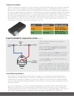
3. Cut the wire and connect the
BLUE
wire from the SID
to the end, which goes toward the key. It should show
about 12V when the key is on Start, but OV otherwise.
4. Connect the
RED
wire from the SID to the other cut
end of the Ignition wire.
5. Connect the
GREEN
wire from the SID to the Green
wire from the tracker. There are a number of videos and
guides on the internet, but note that the relays come
with many different colors of wires. You should go by the
position in the relay socket, not just the color of the wire.
STARTER INTERRUPT (SID) INSTALLATION
Optional
COLOR
FUNCTION
WHAT TO LOOK FOR
Orange
Cellular Network
Blinking = Searching
Solid = Cellular Signal OK
Green
GPS Network
Blinking = Searching
Solid = GPS Signal OK
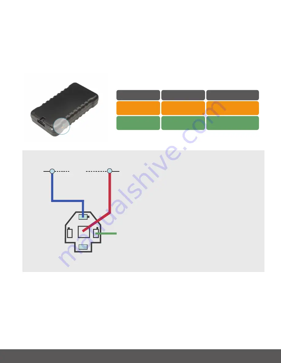
Test the installation by turning the car on and off, opening and closing the driver’s door, and turning lights and dome
lights on and off. Constant power should not be interrupted by these actions, and the device should continue to
operate as you can tell by looking at the lights. When the device is installed with the vehicle off, after approximately
10 seconds of applying power, the device LEDs will begin blinking. The amber LED represents COMM, and the green
LED represents GPS. Once the amber LED is on and no longer blinking (solid) the device has acquired a network
connection. Once the green LED is on and no longer blinking (solid), it has a acquired a GPS fix. The LEDs will remain
on for a period of 5 minutes from the time they begin blinking. Vehicle can be turned on and virtual ignition can
be applied to cause the LEDs to remain powered on. Device label is marked “Label Side Down.” Mounting in this
manner allows for the GPS antenna to be pointed towards the sky.


