background image


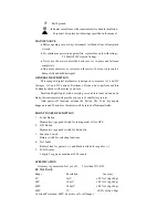
   Earth ground. 


      Indicates compliance with requirements for double insulation. 


    Fuse must be replaced with ratings specified in the manual. 


MAINTENANCE 

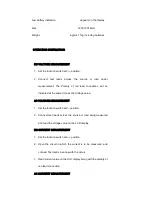
 Before opening case, always disconnect test beads from all energized 

circuits. 

 For continuous protection against fire, replace fuse only with ratings; 

F 500mA/250V (Quick Acting). 

 Never use the meter unless the back cover is in place and fastened 

completely. 

 Do not use abrasives or solvents on the meter. To clean it uses only a 

damp cloth and mild detergent. 

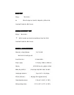
GENERAL DESCRIPTION 

This compact digital multimeter is designed to measure AC and DC 

Voltages, AC and DC current, Resistance, Diode and to perform audible 

Continuity checks with accuracy and ease. 

Small and lightweight, with a carrying case and test leads wound on its 

Body, this instrument will provide you years of satisfactory service. 

Auto power-off function extends the battery life. If no key-inputs 

happen around 30 minutes, this meter will be turned off automatically. 


FRONT PANEL DESCRIPTION 

1.


Power Button   

Momentary-type push switch for tuning meter ON or OFF. 

2.


D-H Button 

Momentary-type push switch for data hold. 

3.


Function Switch 

Rotary switch for selecting functions. 

4.


Test Leads 

Red test lead for positive (+) and black test lead for negative (-) 

5.


LCD Display 

3 digits, 7 segment, maximum 3999 counts 


SPECIFICATION 

    Accuracy is guaranteed for 1 year,23      5,less than 75% RH. 

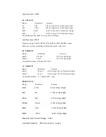
        DC VOLTAGE 

        Range                                    Resolution                                    Accuracy 

        4V                                          1mV                                   

±

0.5% of rdg 

±

2dgt 

      40V                                        10mV                                 

±

0.8% of rdg 

±

2dgt 

        400V                                      100mV                               

±

0.8% of rdg 

±

2dgt 

        600V                                      1V                                       

±

0.8% of rdg 

±

2dgt 

Overload Protection: 600V dc or rms ac for all ranges 

Summary of Contents for MTP-1020

Page 1: ...e you years of satisfactory service DURING USE Never exceed the protection limit indicated in the specifications for each range of measurement Never use the meter to measure voltages that might exceed 600V above earth ground in category installations Always be careful when working with voltages above 60V dc or 30V ac rms keep fingers behind the probe barriers while measuring Do not perform resista...

Page 2: ...uracy and ease Small and lightweight with a carrying case and test leads wound on its Body this instrument will provide you years of satisfactory service Auto power off function extends the battery life If no key inputs happen around 30 minutes this meter will be turned off automatically FRONT PANEL DESCRIPTION 1 Power Button Momentary type push switch for tuning meter ON or OFF 2 D H Button Momen...

Page 3: ...brated in rms of a sine wave DC CURRENT Range Resolution Accuracy 40mA 0 01mA 2 0 of rdg 2dgts 400mA 0 1mA 2 0 of rdg 2dgts Overload Protection F 500mA 250V fuse AC CURRENT Range Resolution Accuracy 40mA 0 01mA 3 0 of rdg 0 5 of full scale 3dgts 400mA 0 1mA 3 0 of rdg 0 5 of full scale 3dgts Overload Protection F 500mA 250V fuse RESISTANCE Range Resolution Accuracy 400Ω 0 1Ω 1 5 of rdg 2dgts 4kΩ 1...

Page 4: ...rms ac GENERAL CHARACTERISTICS Maximum voltage between CAT II 600V Terminals and earth ground Fuse Protection F 500mA 250V Power supply 3V battery SR44 or LR44 X 2 Display LCD 3999 counts updates 2 3 sec Measuring method Dual slope integration A D converter Overrange indication Figure OL on the display Polarity indication _ displayed for negative polarity Operating temperature 0 to 40 32 to 104 St...

Page 5: ...ndicated at the same time as the Voltage value AC VOLTAGE MEASUREMENT 1 Set the function switch at V position 2 Connect test leads across the source or load being measured and read the voltage value on the LCD display DC CURRENT MEASUREMENT 1 Set the function switch at A position 2 Open the circuit in which the current is to be measured and connect Test leads in series with the circuit 3 Read curr...

Page 6: ...easured is connected to a circuit turn off power of the circuit and discharge all capacitors before applying test leads 4 When measuring resistance above 1MΩ the meter will take a few seconds to get stable reading It is normal for high resistance measurement DIODE TEST 1 Set the function switch at position Note The polarity of red lead is Positive 2 Connect the red test lead to the anode of the di...

Page 7: ...ing the function switch BATTERY FUSE REPLACEMENT If the sign appears on the LCD display it indicates that the battery should be replaced Remove the screw on the back cover and open the Case Replace the exhausted batteries with same types Fuse rarely need replacement and blow almost always as a result of Operator s error Open the case and replace blown fuse with same ratings WARNING Before attempti...

Page 8: ...A 250V Accessories Battery SR44 or LR44 Carrying Case Operating manual CAUTION Using this appliance in an environment with a strong radiated radio frequency electromagnetic field approximately 3V m may influence its measuring accuracy The measuring result can be strongly deviating from the actual value ...

Reviews: