background image

Operation 
Note:

 Read and understand all 

warning 

and 

precaution

 statements listed in the safety section of 

this  instruction  manual 

prior

  to  using  the  meter.    Set  the  function  select  switch  to  the 

OFF


position when the meter is not in use. 
 

AC/DC Current Measurement 
 
WARNING :

 Ensure that the test leads are disconnected from the meter before making current 

clamp measurements. 


1.


Set the function switch to 

400A DC, 40A DC, 400A AC or 40A AC

2.


If the range of the measured current is not known, select the higher range first than move 
to the lower range, if necessary. 

3.


Press the trigger to open the jaw.  Fully enclose one conductor to be measured.   

4.


Read the current measurement value on LCD display. 


AC/DC Voltage Measurement 


1.


Insert the black test lead into the negative 

(COM)

 terminal and the red test lead into the 

positive 

(V/Ω/Temp) 

terminal. 

2.


Set the function switch to the "

V"

 position. 

3.


Select AC or DC with the

 MODE

 button. 

4.


Connect the test leads 

in parallel

 to the circuit under test. 

5.


Read the voltage measurement on the LCD display. 


Summary of Contents for MTP-3094

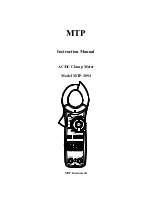
Page 1: ...MTP Instruction Manual AC DC Clamp Meter Model MTP 3094 MTP Instruments...

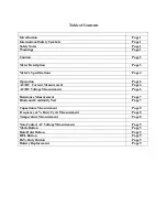
Page 2: ...age 6 AC DC Current Measurement Page 6 AC DC Voltage Measurement Page 6 Resistance Measurement Page 7 Diode and Continuity Test Page 7 Capacitance Measurement Page 8 Frequency or Duty Cycle Measuremen...

Page 3: ...normal use hazardous voltages may be present Double insulation SAFETY NOTES Do not exceed the maximum allowable input range of any function Do not apply voltage to meter when resistance function is s...

Page 4: ...the battery if the meter is to be stored for long periods Always discharge capacitors and remove power from the device under test before performing Diode Resistance or Continuity tests Voltage checks...

Page 5: ...display 10 COM input jack 11 V CAP Temp Hz jack 12 Battery cover Symbolic Display 1 AC DC Alterning current AC and direct current DC 2 Minus sign 3 8 8 8 8 4000 count 0 3999 measurement reading 4 AUT...

Page 6: ...g 2 digits AC Voltage 50 400Hz 4 000 V AC 1 5 of reading 8 digits 40 00 V AC 400 0 V AC 600 0V AC 2 0 of reading 5 digits Resistance 400 0 1 0 of reading 4 digits 4 000k 1 5 of reading 2 digits 40 00k...

Page 7: ...40 C Storage temperature 4 to 140 F 20 to 60 C Operating humidity max of 80 up to 87 F 31 C decreasing linearly to 50 at 104 F 40 C Storage humidity 80 Operating altitude 7000 feet 2000 meters maximu...

Page 8: ...400A AC or 40A AC 2 If the range of the measured current is not known select the higher range first than move to the lower range if necessary 3 Press the trigger to open the jaw Fully enclose one cond...

Page 9: ...the LCD display Diode and Continuity Test 1 Insert the black test lead banana plug into the negative COM jack and the red test lead banana plug into the positive diode jack 2 Turn the rotary switch t...

Page 10: ...a plug into the positive V jack 3 Select Hz or Duty with the Hz button 4 Touch the test probe tips to the circuit under test 5 Read the frequency on the display Temperature Measurement WARNING To avoi...

Page 11: ...s normal operation MODE Button To select DC ACV Ohm Diode Continuity CAP functions DATA HOLD Button To freeze the LCD meter reading press the Data Hold button The Data Hold button is located in the ce...

Page 12: ...ch as misuse improper wiring operation outside of specification improper maintenance or repair or unauthorized modification MTP Instruments specifically disclaims any implied warranties or merchantabi...

Page 13: ...MTP Instruments Head Office 4409 Charleroi street Montreal North Quebec H1H 1T6 Telephone 514 326 7167 Fax 514 326 7835 Toll Free Number 1 888 326 7167 Web Site www mtpinc com E mail info mtpinc com...

Reviews: