background image

Temposonics

®

 E-Series CANopen

Operation Manual

18

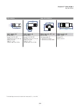
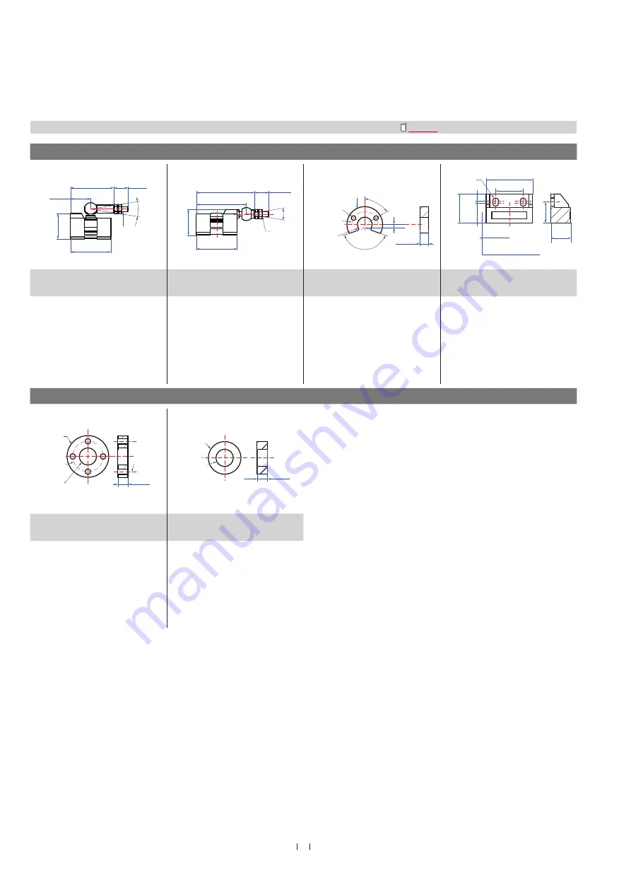
Position magnets

M5

20

(0.79)

43

(1.69)

14

(0.55)

40 (1.58)

18°

25.3 (1)

M5

40 (1.58)

18°

57 (2.24)

14 

(0.55)

25.3 (1)

49 (1.93)

Ø 32.8

(Ø 1.29)

Ø 23.8

(Ø 0.94)
Ø 13.5

(Ø 0.53)

Ø 4.3

(Ø 0.17)

60°

140°

3 (0.12)

7.9

(0.31)

19,5 (0.77)

1,5 (0.06)

33 (1.3)

14

(0.55)

20,5 (0.81)

14,9 (0.59)

8 ± 2 (0.31 ± 0.08)

Space sensor element

Ø 4.3

(Ø 0.17)

Magnet slider S

Part no. 252 182

Magnet slider V

Part no. 252 184

U-magnet OD33

Part no. 251 416-2

Block magnet

Part no. 403 448

For: 

EP and EL

Material: GFK, magnet hard ferrite

Weight: Ca. 35 g

Operating temperature: −40…+75 °C

(−40…+167 °F)

For: 

EP and EL

Material: GFK, magnet hard ferrite

Weight: Ca. 35 g

Operating temperature: −40…+75 °C

(−40…+167 °F)

For: 

EP and EH

Material: PA ferrite

Weight: Ca. 11 g

Surface pressure: max. 40 N/mm

2

Fastening torque for M4 screws: 

Max. 1 Nm

Operating temperature: −40…+105 °C

(−40…+221 °F)

For: 

EP, EL and EH

Material: hard ferrite

Weight: Ca. 20 g

Operating temperature: −40…+75 °C

(−40…+167 °F)

Fastening torque for M4 screws:

Max. 1 Nm

Position magnets

Ø 32.8

(Ø 1.29)

Ø 23.8

(Ø 0.94)

Ø 13.5

(Ø 0.53)

Ø 4.3

(Ø 0.17)

7.9

(0.31)

Ø 25.4

(Ø 1)

Ø 13.5

(Ø 0.53)

 7.9

(0.31)

Ring magnet OD33

Part no. 201 542-2

Ring magnet OD25,4

Part no. 400 533

For: 

EH

Material: PA ferrite GF20

Weight: Ca. 14 g

Surface pressure: max. 40 N/mm

2

Fastening torque for M4 screws:  

Max. 1 Nm

Operating temperature: −40…+105 °C

(−40…+221 °F)

For: 

EH

Material: PA ferrite

Weight: Ca. 10 g

Surface pressure: Max. 40 N/mm

2

Operating temperature: −40…+105 °C

(−40…+221 °F)

Additional options available in our Accessories Guide   551444)

Controlling design dimensions are in millimeters and measurements in ( ) are in inches

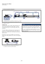
4.7 Frequently ordered accessories – Additional options available in our Accessories Guide 


551444

Summary of Contents for EP00600MD341C304241Z02

Page 1: ...E Series CANopen Operation Manual Temposonics Magnetostrictive Linear Position Sensors...

Page 2: ...essories 18 5 Operation 20 5 1 Encoder functionality system description 20 5 2 Encoder installations configuration of node parameters 21 5 3 Configuration of process parameters 21 5 4 CANopen Network...

Page 3: ...fied automation personnel1 or instructed service technicians who are familiar with the project planning and dealing with Temposonics sensors Before starting the operation of Temposonics sensors read t...

Page 4: ...nit 2 Safety instructions Forseeable misuse Consequence Wrong sensor connection The sensor does not work properly or will be destroyed Operate the sensor out off the operating temperature No signal ou...

Page 5: ...regularly and provide documentation of the checks 7 Before system switch on ensure that nobody s safety is jeopardized by starting machines 2 4 Safety instructions for use in explosion hazardous areas...

Page 6: ...nets i Type 1 Standard h Resolution 4 10 m 5 20 m g Baud rate 1 1000 kBit s 2 500 kBit s 3 250 kBit s 4 125 kBit s c Stroke length X X X X M 0050 2540 mm X X X X U 002 0 100 0 in Standard stroke lengt...

Page 7: ...magnet d Connection type D 3 4 5 pin M12 f Output C 3 0 4 CANopen C 4 0 4 CANopen duo terminator e Operating voltage 1 24 VDC 15 20 g Baud rate 1 1000 kBit s 2 500 kBit s 3 250 kBit s 4 125 kBit s c S...

Page 8: ...ge 1 24 VDC 15 20 g Baud rate 1 1000 kBit s 2 500 kBit s 3 250 kBit s 4 125 kBit s d Connection type D 3 4 5 pin M12 E H 1 2 m PUR cable Part no 530 166 E H 2 5 m PUR cable Part no 530 166 E H 3 10 m...

Page 9: ...Part No Serial number 3 5 Approvals CE certification UL cUL certified 3 6 Scope of delivery E Series EP profile Sensor 2 mounting clamps up to 1250 mm 49 in 1 clamp for each 500 mm 20 in E Series EL l...

Page 10: ...cisely by measuring the time of flight between the application of the current pulse and the arrival of the strain pulse at the sensor head The result is a reliable position measurement with high accur...

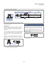
Page 11: ...machine surface using mounting clamps Fig 4 A length dependent number of these clamps are delivered with the sensor and must be distributed over the profile at regular distances For fastening we reco...

Page 12: ...fitted on a flat machine surface using the mounting clamps Fig 7 A length dependent number of these clamps are delivered with the sensor and must be distributed over the profile at regular distances F...

Page 13: ...ing via a 15 3 2 2 O ring in the undercut is possible Fig 9 A screw hole based on ISO 6149 1 Fig 10 must be provided The flange contact surface must be seated completely on the cylinder mounting surfa...

Page 14: ...ar ber zwei M4 Schrauben mit 2 5 mm Innensechkant Anziehmoment max 1 3 Nm U magnet Sensor rod Non magnetic fixing clip 561 481 3 1 0 12 0 04 M4 1 2 Fig 12 Mounting device for U magnet Fig 13 Example o...

Page 15: ...ider 68 2 68 35 1 38 35 1 38 Stroke length Start position Reference edge of mounting 68 2 68 35 1 38 19 0 75 Stroke length Start position Reference edge of mounting Temposonics E Series EP with block...

Page 16: ...E Series EP with block magnet 75 3 75 3 Temposonics E Series EP with magnet slider S V Temposonics E Series EL with magnet slider S V 75 3 75 3 Temposonics E Series EL with block magnet Temposonics E...

Page 17: ...ng ends as large as possible Keep all non shielded leads as short as possible Keep the earth connection as short as possible with a large cross section Avoid ground loops With potential differences be...

Page 18: ...essure max 40 N mm2 Fastening torque for M4 screws Max 1 Nm Operating temperature 40 105 C 40 221 F For EP EL and EH Material hard ferrite Weight Ca 20 g Operating temperature 40 75 C 40 167 F Fasteni...

Page 19: ...no 370 691 CANopen bus terminator Part no 370 700 Housing GD Zn Ni IP67 Termination Screw max 0 75 mm Contact insert CuZn Cable 4 8 mm Fastening torque Max 0 6 Nm Housing GD Zn Ni IP67 Termination Scr...

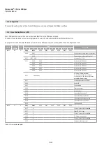
Page 20: ...ity and limit switch states is performed by PDO messages Data is transmitted within four TPDO s transmit PDO and each with a maximum 8 byte wide data block Variable PDO mapping can be configured via S...

Page 21: ...once in a CAN network Valid node IDs range is from 1 127 with 127 being the default setting on delivery Bus termination The internal bus termination resistor with 120 is not attached but can be order...

Page 22: ...his service the NMT master sets the state of the selected NMT slave s to operational 0x02 Stop remote node 5 8 Through this service the NMT master sets the state of the selected NMT slave s to stopped...

Page 23: ...message Table 3 COB ID Rx Tx DLC DATA D0 0x700 Node ID Tx 1 0x00 Network Pre Operational state In the pre operational state communication via SDOs chapter 5 6 is possible while PDO communication is n...

Page 24: ...Set node ID 1 127 0x13 0x00 0x00 Set baud rate 1000 kbit s 0x00 0x01 Set baud rate 800 kbit s 0x00 0x02 Set baud rate 500 kbit s 0x00 0x03 Set baud rate 250 kbit s 0x00 0x04 Set baud rate 125 kbit s 0...

Page 25: ...on 0x7E5 Rx 8 0x13 0x00 0x02 Set baud rate 500 kbit s 0x7E4 Tx 8 0x13 Protocol successfully completed 0x7E5 Rx 8 0x17 Store configuration in EEPROM 0x7E4 Tx 8 0x17 Protocol successfully completed 0x7E...

Page 26: ...e l d 0x0000 Error reset or no error 0x3100 Main voltage generic 0x5000 CANopen device hardware generic error 0x6300 Data set generic 0x8100 Communication generic 0x8110 CAN overrun objects lost 0x812...

Page 27: ...he indication The relationship between producer and consumer is configurable via the object dictionary by SDOs By default the heartbeat is disabled The data byte of the heartbeat message contains the...

Page 28: ...t length specification 0x23 Write 4 bytes 0x2B Write 2 bytes 0x2F Write 1 byte D0 Description 0x43 Upload of 4 bytes 0x4B Upload of 2 bytes 0x4F Upload of 1 byte 5 6 2 SDO upload The SDO upload servic...

Page 29: ...01 0x00 0x00 0x00 0x00 600 Node ID Rx 8 0x40 0x00 0x18 0x01 0x00 0x00 0x00 0x00 Readout transmission types example 580 Node ID Tx 8 0x43 0x00 0x18 0x01 0x80 Node ID 0x01 0x00 0x40 Subindex 2 transmiss...

Page 30: ...0 0x67F Rx 8 0x40 0x00 0x1A 0x01 0x00 0x00 0x00 0x00 Readout of the mapping PDO1 to Position1 0x60200120 0x5FF Tx 8 0x43 0x00 0x1A 0x01 0x20 0x01 0x20 0x60 Subindex 2 PDO mapping for the 2nd applicati...

Page 31: ...x Sub Description Type Attribute Default value Comment 1005 COB ID sync Unsigned 32 rw 0x080 1008 Device name String ro MTS 1009 Hardware version release String ro 1 00 100A Software version release S...

Page 32: ...rw 0x60200220 Position 2 2nd application object Unsigned 32 rw 0x60300210 Velocity 3 3rd application object Unsigned 32 rw 0x64000208 Work area state reg Process Data Object PDO3 1802 0 Transmit 3rd P...

Page 33: ...d 16 rw 0x01 Cycle time in msec 6500 Operating status Unsigned 16 ro 6501 Measuring step Unsigned 32 ro Resolution dependend Measuring step in 0 001 m 6503 Alarms occured Unsigned 16 ro 0x0000 Missing...

Page 34: ...channel 1 Integer 32 rw Start position Sensor units 6402 1 Work area high limit channel 1 Integer 32 rw Max position Sensor units Cam Channel 2 6010 2 Preset value channel 2 Integer 32 rw 0 Sensor un...

Page 35: ...low limit channel 3 Integer 32 rw Start position Sensor units 6402 3 Work area high limit channel 3 Integer 32 rw Max position Sensor units Cam Channel 4 6010 4 Preset value channel 4 Integer 32 rw 0...

Page 36: ...sage can be programmed individually with index 1005 So the COB ID of the sync message may be different depending on the configuration of the sensor NOTICE For the PDO message the measuring steps for t...

Page 37: ...s transmission In case of default PDO mapping hosting 1 PDO with 4 byte position 2 byte velocity and 1 byte for status data the CAN message becomes 103 126 bits depending on stuff bit count Baud rate...

Page 38: ...eshooting See chapter 5 6 2 Maintenance The sensor is maintenance free 6 3 Repair Repairs on the sensor may be performed only by MTS Sensors or an explicitly authorized body 6 4 List of spare parts No...

Page 39: ...Temposonics E Series CANopen Operation Manual 39 7 Removal from service dismantling The product contains electronic components and must be disposed of in accordance with the local regulations...

Page 40: ...IP67 with proper mating connector EH IP69K with proper mating connector Shock test 100 g single shock IEC standard 60068 2 27 Vibration test 15 g 10 2000 Hz IEC standard 60068 2 6 resonance frequenci...

Page 41: ...ck Operating temperature 40 80 C 40 176 F 100 180 C 148 356 F Characteristics Oil resistant energy chain halogen free Operating voltage 24 VDC 15 20 UL Recognition requires an approved power supply wi...

Page 42: ...t MTS Sensors to determine measures to be taken before shipment if necessary Short description of malfunction Corporate information Company Address Contact partner Name Phone E Mail We hereby certify...

Page 43: ...21 6495 6329 info cn mtssensors com www mtssensors com ITALY MTS Systems Srl Sensor Division Via Diaz 4 25050 Provaglio d Iseo BS Italy Tel 39 030 988 38 19 Fax 39 030 982 33 59 info it mtssensors co...

Reviews: