Level Plus
®
Tank SLAYER
®
Operation Manual
I
12
I
1
2
3
4
5
6
7
8
9
10
11
12
13
14
15
16
17
18
19
20
21
22
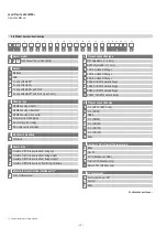
L P T
a
b
c
d
e
f
g
h
i
j
k
l
m
n
o
p
a
Sensor model
L
P T
Tank Slayer
®
Level Transmitter
b Output
M
Modbus
D
DDA
1
1 Loop with HART
®
2
2 Loop with HART
®
5
1 Loop with HART
®
and SIL 2
7
2 Loop with HART
®
and SIL 2 (loop 1 only)
d Electronics mounting
1
Standard
f Materials of construction (Wetted parts)*
1
316L stainless steel
e Sensor pipe
M
Flexible, 7/8"OD tube w/bottom fixing eye
N
Flexible, 7/8"OD tube w/bottom fixing weight
P
Flexible, 7/8"OD tube w/bottom fixing magnet
S
Flexible, 7/8"OD tube w/o bottom fixing hardware
c Housing type
A
NEMA housing w/cable
B
NEMA housing w/terminal
C
NEMA housing w/connector
D
Single cavity with display
E
Dual cavity with display
L
SS single cavity w/display
g Process connection type
1
NPT adjustable (1 in. only)
2
BSPP adjustable (1 in. only)
6
150 lb. welded RF flange
7
300 lb. welded RF flange
8
600 lb. welded RF flange
A
PN16, DIN 2572 welded flange
B
PN40, DIN 2572 welded flange
C
PN64, DIN 2572 welded flange
D
PN100, DIN 2572 welded flange
h Process connection size
B
1 in. (NPT or BSPP only)
D
2 in. (DN50)
E
DN65
F
3 in. (DN80)
G
4 in. (DN100)
H
5 in. (DN125)
J
6 in. (DN150)
X
None
i Number of DT‘s (Digital Thermometers)
0
None
1
One DT
5
5 DTs (Modbus or DDA)
K
Twelve DTs (Modbus only)
M
Sixteen DTs (Modbus only)
j DT‘s placement
F
Evenly spaced per API
C
Custom
X
None
*/
Contact factory for other materials
5.6 Model number identification
Continued on next page…

