background image

Level Plus

® 

Tank SLAYER

®

Operation Manual

I

 63 

I

Summary of Contents for Level Plus Tank SLAYER

Page 1: ...Operation Manual Level Plus Magnetostrictive Liquid Level Transmitters with Temposonics Technology Tank SLAYER...

Page 2: ...llation steps 15 6 5 Mounting 16 7 Electrical connections 17 7 1 Basic information 17 7 2 Safety recommendations 17 7 3 Industrial topologies 17 7 4 Cable recommendations 18 7 5 Electrical conduit 18...

Page 3: ...rvice Tel 1 800 633 7609 Fax 1 800 498 4442 E mail info us mtssensors com Technical support and applications 24 Hour Emergency Technical Support Tel 1 800 633 7609 E mail levelplus mts com Germany Gen...

Page 4: ...explosion to the explosive gas atmosphere surrounding the enclosure G GOVI Gross Observed Volume of the Interface The total volume of the tank occupied by the interface liquid The GOVI is only given...

Page 5: ...density measurement is given the allowable values are 32 F to 150 F 0 C to 66 C S Specific Gravity The density ratio of a liquid to the density of water at the same conditions Sphere Radius The intern...

Page 6: ...OTICE This symbol is used to point to situations that may lead to material damage and or personal injury 4 Safety instructions 4 1 Intended use The liquid level transmitter is intended to be used to m...

Page 7: ...ame resistant clothing safety glasses gloves and hearing protection 2 Follow the specifications given in the technical documentation 3 Two 2 individuals are recommended to conduct proper installation...

Page 8: ...Features 4 in 1 Measurement Product Level Interface Level Temperature Volume No scheduled maintenance or recalibration Field Repairable Inherent Accuracy 1mm 200 Point Strap Table API Temperature Corr...

Page 9: ...ED OR DISCLOSED IN ANY FORM EXCEPT AS GRANTED IN WRITING BY MTS SYSTEMS CORPORATION THIS RESTRICTION EXCLUDES INFORMATION THAT IS IN THE PUBLIC DOMAIN OR WAS LEGITIMATELY IN THE PRIOR POSSESSION OF TH...

Page 10: ...the stylus make sure to align the stylus with the shape outline around the buttons in the same orientation Failure to correctly align the stylus can cause the display to not function properly Passwor...

Page 11: ...No Flange 725 psig 50 0 bar 603 psig 41 6 bar 150 275 psig 19 0 bar 235 psig 16 2 bar 223 psig 15 4 bar 300 720 psig 49 6 bar 620 psig 42 7 bar 585 psig 40 3 bar 600 1440 psig 99 3 bar 1240 psig 85 5...

Page 12: ...EMA housing w cable B NEMA housing w terminal C NEMA housing w connector D Single cavity with display E Dual cavity with display L SS single cavity w display g Process connection type 1 NPT adjustable...

Page 13: ...with C CEC FMC notified body and F Flameproof Explosion proof protection method B Group B C Group C D Group D 3 IIC Instrinsically Safe only 4 IIB H2 Explosion Proof Flameproof only X None n Unit of m...

Page 14: ...00 4 3 EN 61000 4 4 EN 61000 4 5 EN 61000 4 6 EN 61000 4 8 EN 61000 4 11 Environmental Enclosure Rating NEMA Type 4X IP65 Humidity 0 100 relative humidity non condensing Operating Temperatures Electro...

Page 15: ...screwdriver 6 4 Installation steps Caution When assembling and installing the Tank Slayer transmitter be careful not to allow the flexible hose to kink or be coiled in less than 406 5 mm 16 in diamet...

Page 16: ...of transmitter is being mounted There are two typical methods for mounting threaded flange mounting and welded flange mounting Threaded flange mounting In most applications the Tank Slayer transmitte...

Page 17: ...ice Refer to Agency information in chapter 13 A typical Explosionproof flame proof connection for the Level Plus Tank Slayer transmitter includes a power supply and a reading or monitoring device All...

Page 18: ...le specifications 7 5 Electrical conduit Parameter Specifitcation Minimum cable size 0 51 1 6 mm 24 14 AWG Cable type Single pair shielded or multiple pair with overall shield minimum 0 25 mm 0 010 in...

Page 19: ...ng performance of the communication cable and possible degradation in performance of the sensor In this case a braided type shielded cable connected to the sensor internal ground lug would be recommen...

Page 20: ...ult chapter 4 3 before starting 2 Remove level transmitter from shipping container 3 Remove bottom fixing nut washer spacer and stop collar 4 Insert flexible hose into float s making sure float s are...

Page 21: ...nance dependent on the application For general purpose applications where there is no potential for buildup on the flexible hose and or float there is no need for preventative maintenance but routine...

Page 22: ...ed PC Linear Regulated Power Supply HART to USB Converter MTS Part 380068 HART 10 4 Troubleshooting 10 5 Setup software MTS offers Setup Software that is shipped with the level transmitter and is also...

Page 23: ...l Access over a RS485 half duplex network For additional information consult DDA Interface Manual MTS Part 551701 12 3 HART MTS offers HART over a 4 to 20 mA signal For additional information consult...

Page 24: ...2016 CAN CSA C22 2 No 61010 1 2012 CSA C22 2 No 60529 R2010 E ATEX I Instrinsic Safety II 1 2 G Ex ia IIC T4 Ta 50 C to 71 C IP65 EN 60079 0 2012 EN 60079 11 2012 EN 60529 1991 A1 2000 F Flame proof...

Page 25: ...s of the equipment containing light metals Aluminum or Titanium shall be protected from impact so that impact or friction sparks cannot occur taking into account rare malfunction Measures to prevent i...

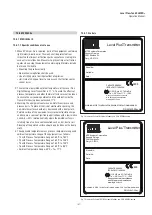
Page 26: ...18 Intrinsically Safe FM label Modbus or DDA NEMA Housing Fig 19 Intrinsically Safe FM label HART NEMA Housing Fig 20 Intrinsically Safe FM label Modbus or DDA Single or Dual Cavity Housing Fig 21 Int...

Page 27: ...LFUNCTION MEASURES TO PREVENT IMPACT OR FRICTION SPARKS WHEN USING THE EQUIPMENT CONTAINING LIGHT METALS INCLUDE BUT ARE NOT LIMITED TO MOUNTING THE PROBE VERTICALLY NO MECHANICAL AGITATION SHALL BE U...

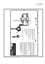
Page 28: ...MTS SYSTEMS CORPORATION SENSORS DIVISION 3001 SHELDON DRIVE CARY NC 27513 METRIC FIRST ANGLE D 651543 1 2 2 DRAWN BY MS NO REVISIONS SHALL BE MADE WITHOUT THE NOTIFICATION TO APPROVAL AGENCY S H C 78...

Page 29: ...CUSTOMER CONNECTIONS WILL BE MADE AT TERMINAL BLOCK ON POWER SIDE OF HOUSING NOT TO TERMINAL BLOCK ON INTERCONNECT BOARD EARTH GROUND LUG NOTE 3 AGENCY CONTROLLED DRAWING US NO CHANGES WITHOUT PRIOR A...

Page 30: ...N SENSORS DIVISION 3001 SHELDON DRIVE CARY NC 27513 METRIC FIRST ANGLE D 651544 1 LEVEL 2 2 DRAWN BY MS NO REVISIONS SHALL BE MADE WITHOUT THE NOTIFICATION TO APPROVAL AGENCY S H C 7898 UPDATED TEMPER...

Page 31: ...OSION PROOF FOR CL I DIV 1 GR BCD T6 T3 CL I ZONE 0 1 AEx db IIB H2 T6 T3 Ga Gb Ta 40 C TO 71 C IP 65 INPUT 28V 120mA max OUTPUT RS485 WARNING DO NOT OPEN WHEN AN EXPLOSIVE ATMOSPHERE IS PRESENT FOR Z...

Page 32: ...CK ON INTERCONNECT BOARD SEE FIGURE 2 ON PAGE 2 3 CAUTION FLEXIBLE GAUGES HAVE A MINIMUM BEND RADIUS OF 381mm 15 4 WARNING TO PREVENT IGNITION OF FLAMMABLE OR COMBUSTIBLE ATMOSPHERES DISCONNECT POWER...

Page 33: ...IS RESTRICTION EXCLUDES INFORMATION THAT IS IN THE PUBLIC DOMAIN OR WAS LEGITIMATELY IN THE PRIOR POSSESSION OF THE RECIPIENT m MTS SYSTEMS CORPORATION SENSORS DIVISION 3001 SHELDON DRIVE CARY NC 2751...

Page 34: ...ION OF FLAMMABLE OR COMBUSTIBLE ATMOSPHERES DISCONNECT POWER BEFORE SERVICING 5 WARNING THE EQUIPMENT CONTAINS NON METALLIC ENCLOSURE AND PROCESS PARTS TO PREVENT THE RISK OF ELECTROSTATIC SPARKING TH...

Page 35: ...N WRITING BY MTS SYSTEMS CORPORATION THIS RESTRICTION EXCLUDES INFORMATION THAT IS IN THE PUBLIC DOMAIN OR WAS LEGITIMATELY IN THE PRIOR POSSESSION OF THE RECIPIENT m MTS SYSTEMS CORPORATION SENSORS D...

Page 36: ...Corporation Sensors Division 3001 Sheldon Dr Cary NC 27513 Model No Mod le No Serial No Num ro de s rie Date R USE MTS LOGO ARTWORK 10 POINT SIZE 8 POINT TEXT SIZE 4 5 POINT TEXT SIZE MTS TO PRINT MO...

Page 37: ...utions d installations ATTENTION La substitution de composants peut compromettre la s curit intrins que LPXXXXXXXXXXXXXXXXXXXX XXXXXXXXX XX XX R FM C APPROVED Level Plus Transmitter P N 551704 X Rev F...

Page 38: ...DIRECTLY OR THROUGH THE EQUIPMENT ON WHICH IT IS MOUNTED 5 CONTROL EQUIPMENT CONNECTED TO ASSOCIATED APPARATUS MUST NOT USE OR GENERATE MORE THAN 250 VRMS OR VDC 6 ASSOCIATED APPARATUS MANUFACTURER S...

Page 39: ...543 2 2 3 DRAWN BY MS NO REVISIONS SHALL BE MADE WITHOUT THE NOTIFICATION TO APPROVAL AGENCY S H C 7898 UPDATED TEMPERATURE ON NOTE 12 TO 71 C MS 2 23 15 D 8037 ADDED WIRING CHART MS 11 3 15 E 8183 AD...

Page 40: ...que avec un appareil associ lorsque la suivante est vraie Vmax or Ui Voc Vt or Uo Imax or Ii Isc It or Io Pmax or Pi Po Ca Ci Ccable La Li Lcable 10 ENCEINTES cavit double Les raccordements clients s...

Page 41: ...N POWER SIDE OF HOUSING NOT TO TERMINAL BLOCK ON INTERCONNECT BOARD EARTH GROUND LUG NOTE 3 AGENCY CONTROLLED DRAWING Canada NO CHANGES WITHOUT PRIOR AGENCY APPROVAL AGENCE DESSIN contr l e CANADA AUC...

Page 42: ...651544 2 LEVEL 2 3 DRAWN BY MS NO REVISIONS SHALL BE MADE WITHOUT THE NOTIFICATION TO APPROVAL AGENCY S H C 7898 UPDATED TEMPERATURE ON NOTE 12 TO 71 C MS 2 23 15 D 8037 ADDED WIRING CHART MS 11 3 15...

Page 43: ...ue boucle Ui 28 VDC Ii 120 mA Ci 0 F Li 5 H Pi 840 mW 10 ENCEINTES cavit double Les raccordements clients seront effectu s au bornier d alimentation sur le c t du LOGEMENT bo tier pas au bornier carte...

Page 44: ...TIONS A SEAL SHALL BE INSTALLED WITHIN 50mm OF THE ENCLOSURE FOR DIVISION INSTALLATIONS A SEAL SHALL BE INSTALLED WITHIN 18 INCHES OF THE ENCLOSURE ATTENTION NE PAS OUVRIR UNE ATMOSPH RE EXPLOSIVE PRE...

Page 45: ...E FIGURE 2 ON PAGE 2 3 CAUTION FLEXIBLE GAUGES HAVE A MINIMUM BEND RADIUS OF 381mm 15 4 WARNING TO PREVENT IGNITION OF FLAMMABLE OR COMBUSTIBLE ATMOSPHERES DISCONNECT POWER BEFORE SERVICING 5 WARNING...

Page 46: ...VISION 3001 SHELDON DRIVE CARY NC 27513 METRIC FIRST ANGLE D 651553 2 C LEVEL 2 3 DRAWN BY MS NO REVISIONS SHALL BE MADE WITHOUT THE NOTIFICATION TO APPROVAL AGENCY S A 7957 RELEASED TO PRODUCTION MS...

Page 47: ...ECTEZ UN PANNEAU DE PLAISIR LA SURFACE PEINT E DE L QUIPEMENT PEUT CONSERVER LE CHARGE LECTROSTATIQUE ET DEVENIR UNE SOURCE D ALLUMAGE DANS DES APPLICATIONS AVEC UNE HUMIDIT BASSE RELATIVE 30 RELATIVE...

Page 48: ...5 4 WARNING TO PREVENT IGNITION OF FLAMMABLE OR COMBUSTIBLE ATMOSPHERES DISCONNECT POWER BEFORE SERVICING 5 WARNING THE EQUIPMENT CONTAINS NON METALLIC ENCLOSURE AND PROCESS PARTS TO PREVENT THE RISK...

Page 49: ...RECIPIENT m MTS SYSTEMS CORPORATION SENSORS DIVISION 3001 SHELDON DRIVE CARY NC 27513 METRIC FIRST ANGLE D 651552 2 C 2 3 DRAWN BY MS NO REVISIONS SHALL BE MADE WITHOUT THE NOTIFICATION TO APPROVAL AG...

Page 50: ...NNEAU DE PLAISIR LA SURFACE PEINT E DE L QUIPEMENT PEUT CONSERVER LE CHARGE LECTROSTATIQUE ET DEVENIR UNE SOURCE D ALLUMAGE DANS DES APPLICATIONS AVEC UNE HUMIDIT BASSE RELATIVE 30 RELATIVE HUMIDITE O...

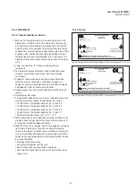
Page 51: ...e of 40 C to 150 C T4 with Process Temperature Range of 40 C to 135 C T5 with Process Temperature Range of 40 C to 100 C T6 with Process Temperature Range of 40 C to 85 C Ambient Temperature Range 40...

Page 52: ...us Transmitter P N 551705 X Rev E MTS Systems Corporation Sensors Division 3001 Sheldon Drive Cary N C 27513 II 1 2 G Ex ia IIC T4 Ga Gb Ta 50 C TO 71 C IP65 WARNING SUBSTITUTION OF COMPONENTS MAY IMP...

Page 53: ...CONTROL EQUIPMENT CONNECTED TO ASSOCIATED APPARATUS MUST NOT USE OR GENERATE MORE THAN 250 VRMS OR VDC 6 ASSOCIATED APPARATUS MANUFACTURER S INSTALLATION DRAWING MUST BE FOLLOWED WHEN INSTALLING THIS...

Page 54: ...ION SENSORS DIVISION 3001 SHELDON DRIVE CARY NC 27513 METRIC FIRST ANGLE D 651543 3 LEVEL 2 2 ACP INSTALLATIN DWG LP DIGITAL INTRINSICALLY SAFE FOR ATEX IEC DRAWN BY MS NO REVISIONS SHALL BE MADE WITH...

Page 55: ...BLES RUN LOOPS IN SEPARATE GROUNDED SHIELDS 9 ENTITY PARAMETERS EACH LOOP Ui 28 VDC Ii 120 mA Ci 0 F Li 5 H Pi 840 mW 10 DUAL CAVITY ENCLOSURES CUSTOMER CONNECTIONS WILL BE MADE AT TERMINAL BLOCK ON P...

Page 56: ...3001 SHELDON DRIVE CARY NC 27513 METRIC FIRST ANGLE D 651544 3 LEVEL 2 2 ACP INSTALLATIN DWG LP ANALOG INTRINSICALLY SAFE FOR ATEX IEC DRAWN BY MS NO REVISIONS SHALL BE MADE WITHOUT THE NOTIFICATION T...

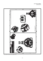
Page 57: ...he electronic head and pressure barrier have a minimum spacing of 5 inches See Installation Manual for detail 9 When EPL Ga or Da is required parts of the equipment containing light metals Aluminum or...

Page 58: ...TMOSPHERES DISCONNECT POWER BEFORE SERVICING 5 WARNING THE EQUIPMENT CONTAINS NON METALLIC ENCLOSURE AND PROCESS PARTS TO PREVENT THE RISK OF ELECTROSTATIC SPARKING THE NON METALLIC SURFACE AND PROCES...

Page 59: ...TING BY MTS SYSTEMS CORPORATION THIS RESTRICTION EXCLUDES INFORMATION THAT IS IN THE PUBLIC DOMAIN OR WAS LEGITIMATELY IN THE PRIOR POSSESSION OF THE RECIPIENT m MTS SYSTEMS CORPORATION SENSORS DIVISI...

Page 60: ...TO PREVENT THE RISK OF ELECTROSTATIC SPARKING THE NON METALLIC SURFACE AND PROCESS PARTS SHOULD ONLY BE CLEANED WITH A DAMP CLOTH PAINTED SURFACE OF THE EQUIPMENT MAY STORE ELECTROSTATIC CHARGE AND BE...

Page 61: ...UCED OR DISCLOSED IN ANY FORM EXCEPT AS GRANTED IN WRITING BY MTS SYSTEMS CORPORATION THIS RESTRICTION EXCLUDES INFORMATION THAT IS IN THE PUBLIC DOMAIN OR WAS LEGITIMATELY IN THE PRIOR POSSESSION OF...

Page 62: ...Level Plus Tank SLAYER Operation Manual I 62 I 13 5 3 EC Declaration of conformity...

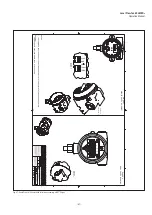
Page 63: ...Level Plus Tank SLAYER Operation Manual I 63 I...

Page 64: ...hone 81 3 6416 1063 E mail info jp mtssensors com www mtssensors com MTS Temposonics and Level Plus are registered trademarks of MTS Systems Corporation in the United States MTS SENSORS and the MTS SE...

Reviews: