background image

Interface Manual HART

®

Operation Manual

Level Plus

®

Magnetostrictive Liquid Level Transmitters

with Temposonics

®

 Technology

Summary of Contents for Level Plus

Page 1: ...Interface Manual HART Operation Manual Level Plus Magnetostrictive Liquid Level Transmitters with Temposonics Technology ...

Page 2: ...ngs 6 4 Safety instructions 6 4 1 Intended use 6 5 Product overview 6 5 1 Before you begin 6 5 2 Quick start up procedure 6 6 Display Menu 6 6 1 Operation Modes 7 6 2 Display Diagram 7 6 3 Menu Structure 8 7 Alarms 8 7 1 Software Fault Alarm 8 7 2 Hardware Fault Alarm 8 8 Alarms 9 9 HART Interface 10 9 1 LP Dashboard 10 9 2 Handheld Programming 14 ...

Page 3: ...ervice Tel 1 800 633 7609 Fax 1 800 498 4442 E mail info us mtssensors com Technical support and applications 24 Hour Emergency Technical Support Tel 1 800 633 7609 E mail levelplus mts com Germany General Tel 49 2351 9587 0 Fax 49 2351 56491 E mail info de mtssensors com http www mtssensors com Mailing and shipping address MTS Sensor Technologie GmbH Co KG Auf dem Schüffel 9 58513 Lüdenscheid Ger...

Page 4: ...e surrounding the enclosure G GOVI Gross Observed Volume of the Interface The total volume of the tank occupied by the interface liquid The GOVI is only given when measuring two liquids and is calculated by subtracting the volume of the product from the total volume of liquid in the tank GOVT GOVP GOVP Gross Observed Volume of the Product The total volume of the tank occupied by the product liquid...

Page 5: ...ty The density ratio of a liquid to the density of water at the same conditions Sphere Radius The internal radius of the sphere that contains the liquid the value is used to calculate the volume along with the Sphere Offset Sphere Offset An offset value that accounts for additional volume in a sphere from non uniform sphere geometry the value is used to calculate the volume along with the Sphere R...

Page 6: ...n of the 4 and 20 mA set points Tools needed 24 Vdc linear regulated power supply Current meter 5 2 Quick start up procedure 1 Connect 24 Vdc power supply to Loop 1 2 Turn on power supply 3 Connect Current Meter to test pins on interconnect board Loop 1 Test Pins are on the bottom left and labeled TP1 and TP2 4 Move the float towards the tip of the pipe and verify 4 mA set point 5 Move the float t...

Page 7: ...to incoming HART commands A busy error will be sent to the controller to notify the unit is in program mode This function will prevent a user at a remote terminal from programming the unit while a user is accessing program mode from the display Fig 1 Display 6 2 Display Diagram Key Element Function UP Arrow Used to move cursor on screen up and to increment number DOWN Arrow Used to move cursor on ...

Page 8: ...actory 7 Alarms MTS has two separate types of alarms featuring both a software fault alarm and a hardware fault alarm 7 1 Software Fault Alarm MTS offers a software fault alarm that will force the 4 20 mA output into an either a low or high alarm state The default setting from the factory is a low alarm state The low alarm state is 3 6 mA and the high alarm state is 21 mA The software fault alarm ...

Page 9: ...act Factory 117 Timing Fault 3 Cycle power to sensor If proper operation is not restored Contact Factory Fault Code Description Corrective Action 118 DAC Fault 1 Cycle power to sensor If proper operation is not restored Contact Factory 119 DAC Fault 2 Cycle power to sensor If proper operation is not restored Contact Factory 120 DAC Fault 3 Cycle power to sensor If proper operation is not restored ...

Page 10: ...t the HART to USB converter to the PC Example setup shown below NOTICE Power must be on Loop 1 for HART communication to work Power does not have to be applied on Loop 2 for HART to work Power must be applied to Loop 2 to check current output NOTICE HART requires a load resistor to work correctly Add a 250 Ohm resistor for proper communication Some PLC cards will have built in load resistors Fig 2...

Page 11: ...dered with a second loop User Configurable Reverse Measure Allows the end user to change the direction in which the MTS level transmitter counts The default setting is OFF and the level transmitter will reference the tip of the pipe hose and count up from the tip The ON setting will reference the head of the level transmitter and count up as it moves towards the tip Device Address The end user can...

Page 12: ...its Default is inches if ordered in inches and mm if ordered in mm Options include inches feet millimeters centimeters and meters Method Enter Current Tank Level a calibration method that calibrates the level transmitter based off of one point of measurement Select Enter Current Tank Level from the Method drop down box Go to Product Level and enter value of current product level based off of a man...

Page 13: ...up after completing testing and calibration at the MTS factory MTS can provide a copy of the backup file upon request based off of the serial number of the level transmitter Contact MTS Technical Support for assistance User Configurable Reset to Factory Defaults Allows the end user to reset all settings back to the original settings as they were when they left the MTS factory This is intended to b...

Page 14: ...etailed Setup Variable mapping Configuration Sys Config Alarm Level 1 Level 2 Temperature Display Display Setting Lobe Count Gradient Offsets Float 1 Offset Float 2 Offset LCD settings Screen delay Screen contrast Sensors Level 1 Level 1 Unit Level 1 Level 1 Class Level 1 LRV Level 1 URV Level 1 Min Span Level 1 Damp Level 2 Level 2 Unit Level 2 Level 2 Class Level 2 LRV Level 2 URV Level 2 Min Sp...

Page 15: ... variables can be changed and the full menu tree cannot be seen Data No Data is displayed 9 4 2 3 Process variables Menu Screen Parameters PV Primary Variableis the HART parameter that is by default mapped to the Product Level This can be changed using Variable mapping feature SIL2 Capable units do not allow the PV to be changed SV Secondary Variable is the HART parameter that is mapped to the Int...

Page 16: ... location of the 20 mA set point of the output Data Level 2 the interface level is displayed SV rnge the percentage 0 to 100 of the active range that the process variable is currently at SV Loop current the current output level of the SV based on the settings of the LRV URV and Level 2 9 4 2 6 TV Menu Screen Parameters Temp LRV lower range value of the TV that correlates to the location of the 4 m...

Page 17: ...Tree Parameters 4 mA allows the user to force loop test and current output to 4 mA 20 mA allows the user to force loop test and current output to 20 mA Other allows the user to force loop test and current output to selected level End Stops loop test and returns level transmitter to normal output Data No data is displayed 9 4 2 11 Basic setup Menu Screen Parameters Tag HART descriptor that can be e...

Page 18: ...select the MTS variable that is mapped to the SV in HART TV is allows user to select the MTS variable that is mapped to the TV in HART Data No data is displayed 9 4 2 14 Configuration Menu Screen Parameters Sys Config allows access to MTS factory parameters Gradient calibration factor for level transmitter that should not be changed unless replacing a sensing element Data No data is displayed 9 4 ...

Page 19: ...llows user to change the offset of the interface level that is used for calibration Please contact the factory for technical support to make this change Data No data is displayed 9 4 2 17 LCD settings Menu Screen 9 4 2 18 Sensors Menu Screen Parameters Level 1 allows user to access parameters and data for product level Level 2 allows user to access parameters and data for interface level Temp allo...

Page 20: ...el 2 LRV lower range value of the interface level that correlates to the location of the 4 mA set point of the output Level 2 URV upper range value of the interface level that correlates to the location of the 20 mA set point of the output Level 2 Damp damping parameter for interface level Data Level 2 actual product level in units of measure Level 2 Class variable class for interface level Level ...

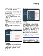
Page 21: ...een 9 4 2 22 HART output Menu Screen Parameter Poll addr allows user to change polling address of HART device Unless using HART in multidrop network do not change Poll addr from default value of 0 Num req preams changes the HART preamble Do not adjust Data No data displayed ...

Page 22: ...jp mtssensors com www mtssensors com MTS Temposonics and Level Plus are registered trademarks of MTS Systems Corporation in the United States MTS SENSORS and the MTS SENSORS logo are trademarks of MTS Systems Corporation within the United States These trademarks may be protected in other countries All other trademarks are the property of their respective owners Copyright 2018 MTS Systems Corporati...

Reviews: