- 12 -
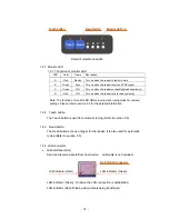
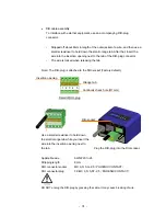
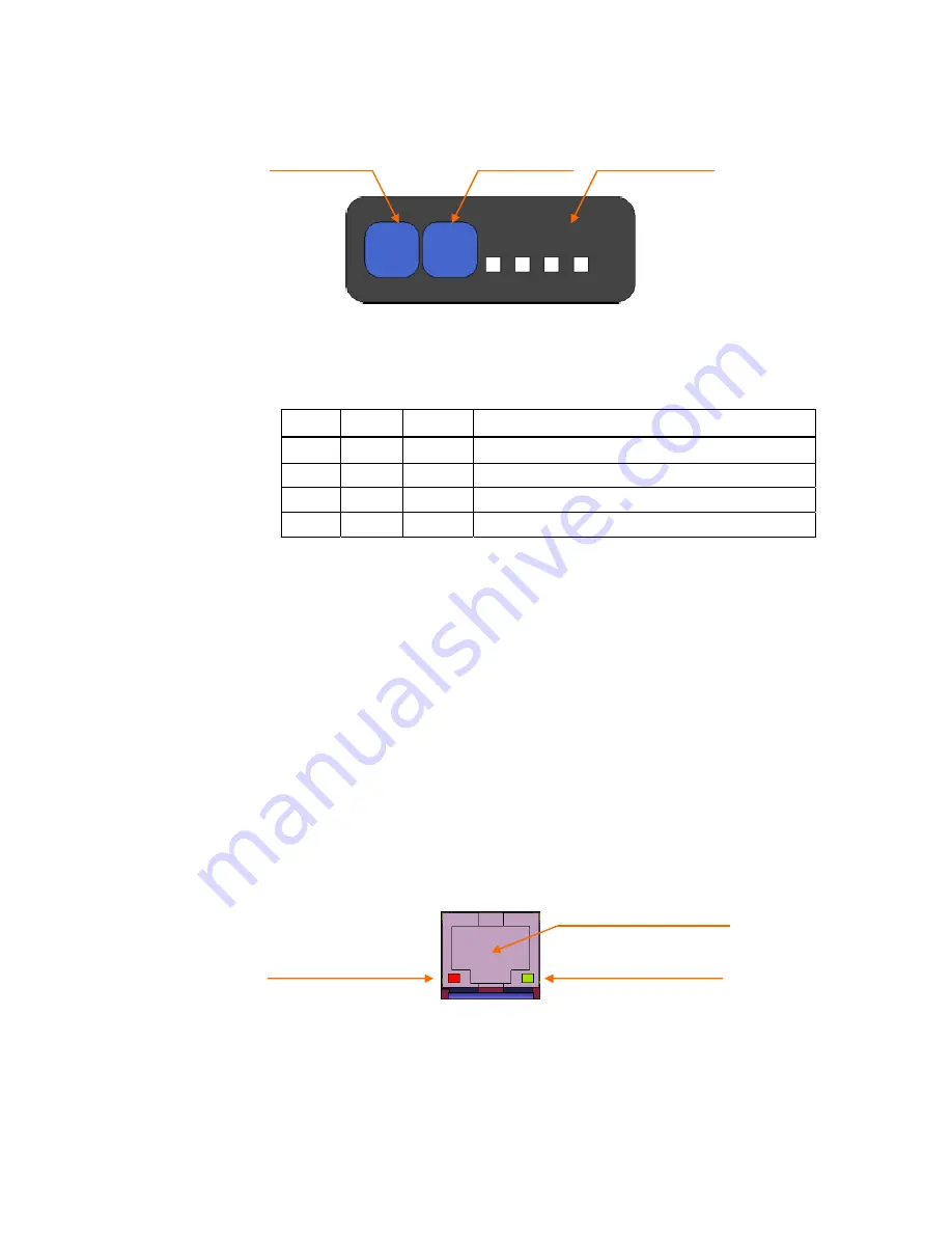
1.2.1 Monitor LED
1.2.1.1 Function of monitor LED
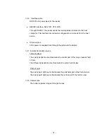
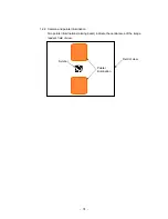
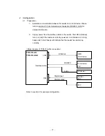
Note: The function of monitor LED differs in automatic tuning mode for camera
settings. Please refer to section 5.5 for the detailed information.
1.2.2 Teach button
The Teach button is used for automatic tuning (Refer to section 5.5).
1.2.3 Read button
The Read button acts as a trigger for the reader. It is also used for automatic
tuning (Refer to section 5.5).
1.2.4 LAN connector
•
LAN interface (LAN)
Send and receive data to/from host device. LAN cable is not included.
LAN indicator (Green): On when the LAN connection is established.
LAN indicator (Red): Blinking when data is being transferred.
LED Color Name Description
A
Red
Ready
Turn on when the reader is ready to work
B
Green
Sync
Turn on when the reader receives SYNC signal
C
Green
GO
Turn on when the reader successfully reads symbol(s)
D
Red
NG
Turn on when the reader fails to read symbol(s)
Detail of membrane switch
C
B
A
Teach
Read
D
Monitor LED × 4
Read button
Teach button
LAN indicator (Green)
LAN indicator (Red)
RJ-45(LAN) connector
Summary of Contents for TFIR-31LAN series
Page 2: ...Update Information Edition Date Update Contents 1st edition 2012 06 13 New release...
Page 3: ...1...
Page 89: ...87 7 14 Table of Character code...
Page 91: ...89...
Page 101: ...99 Memorandom...
Page 102: ...100 Memorandom...
Page 103: ...101 Memorandom...
Page 104: ......


