User's Manual
MS3707H Slim Plug-In Distributor with Isolated Single Output with HART Communication
Rev. 1.10
4
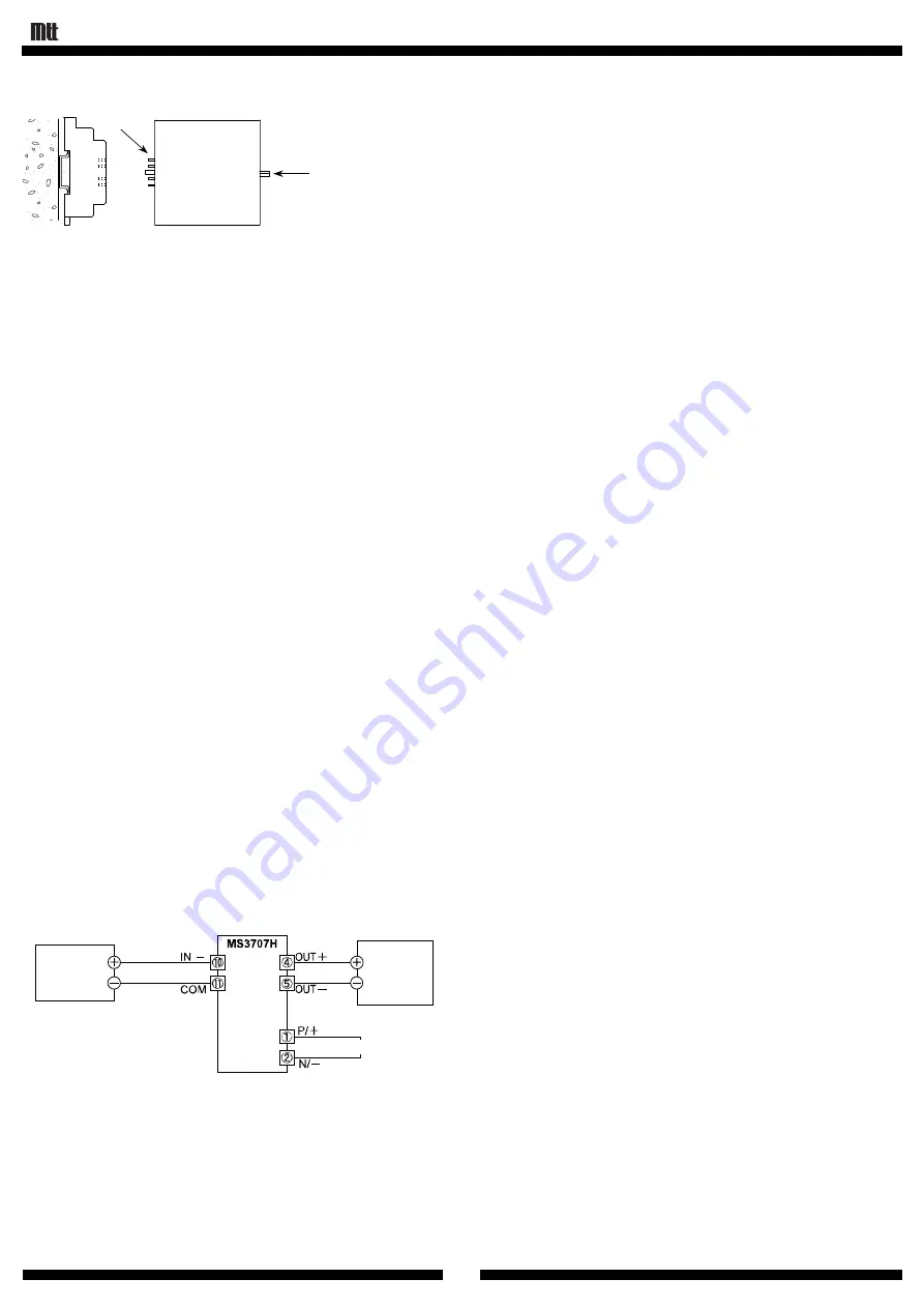
Main Unit Installation / Removal
Fixing Screw
I/O Pins
Installation
(1) Identify the top and the bottom of the unit and insert the I/O pins
straight into the corresponding pin slots (receptacles) on the
socket.
(2) Tighten the fixing screw to fix the unit firmly in position.
Removal
(1) Loosen the fixing screw.
(2) Pull out the unit carefully not to bend the I/O pins.
10. Adjustment
Since the unit is precisely factory-adjusted before shipment, no
further adjustment is needed at the user’s side. Adjustment of signal
conditioners requires technical expertise and fine craftsmanship. We
recommend that you use adjustment service of MTT to save costs
and ensure accuracy. Please contact MTT or its local
representatives. Just for your reference, the adjustment procedure
is described below.
10-1. Preparation
For the terminal assignments, refer to section 5.
The wiring work should be performed with no power applied to
the instrument.
Wiring should be connected to the terminal block.
At least 30 minutes of warm-up is required before adjustment.
The accuracy of measuring equipment to be used for calibration
must be much higher than that of the instrument to be adjusted.
10-2. Adjustment Procedure
(1) Connect the unit as illustrated below.
(2) Adjust the current source to generate a signal equivalent to 0%
of the input range of the unit.
(3) Slowly turn the ZERO Trimmer to get 0% output while applying
0% input as above.
(4) Adjust the current source to generate a signal equivalent to
100% of the input range of the unit.
(5) Slowly turn the SPAN Trimmer to get 100% output while
applying 100% input as above.
(6) Repeat steps (2) through (5) until zero and span are precisely
adjusted.
(7) Adjust the current source to generate 25%, 50% and 75% of the
input signal range of the unit and record the values of output
signals to confirm they are linearly proportional.
CALIBRATED
ADJUSTABLE
CURRENT
SOURCE
(4-20mA)
MULTIMETER
POWER SUPPLY
11. Maintenance and Inspection
Check the unit for proper characteristics and settings about once
every two years.
12. Warranty Period and Scope
[Warranty Period]
MTT’s hardware products are warranted for a period of seven (7)
years from the date of shipment.
[Warranty Scope]
1) MTT warrants that its hardware products are free from defects
in materials and workmanship and conform to its product
specifications.
2) MTT ships the products under its appropriate quality
management system and quality control, but does not warrant,
expressed or implied, that the operation, output, or indication
of the hardware will be uninterrupted or error free. MTT shall
not be liable and make no warranty for any damage to or any
safety or performance trouble in the customer’s or any other
third party’s equipment if the operation, output, or indication is
interrupted or faulty.
3) If, during the warranty period, the product proves to be
defective when used in accordance with the relevant user’s
manual, the product will be repaired or replaced.
4) This warranty does not apply to any malfunction or failure
resulting from the following:
a. Improper or incomplete maintenance or calibration,
b. Any other cause, which does not relate with the delivered
product,
c. Modification or repair by any person other than MTT, and
d. Natural disasters or other unavoidable accidents, for which
MTT is not liable.


