8.
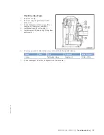
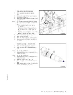
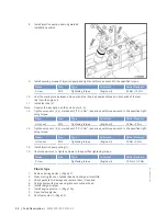
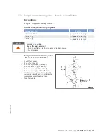
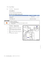
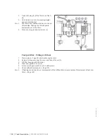
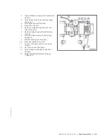
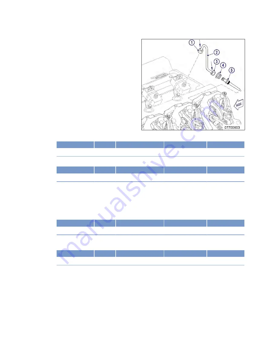
Blow out fuel line (2) and pressure pipe
neck (5) with compressed air.
9.
Coat sealing ring with grease and fit onto
pressure pipe neck (5).
10.
Coat the tape of the pressure pipe neck (5)
with engine oil.
11.
Insert pressure pipe neck (5) into cylinder
head until the sealing ring is in contact with
cylinder head.
12.
Fully press in pressure pipe neck (5) by
hand.
13.
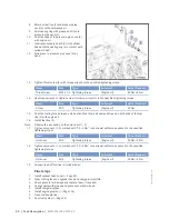
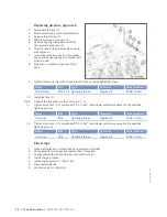
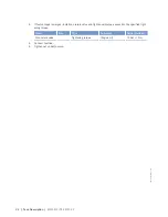
Tighten thrust screw (4) with torque wrench to the specified tightening torque.
Name
Size
Type
Lubricant
Value/Standard
Thrust screw
M22 x 1.5 Tightening torque
(Engine oil)
40 Nm ±5 Nm
14.
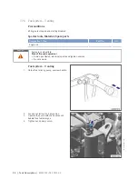
Use torque wrench to tighten screw for clamp at injector to the specified tightening torque.
Name
Size
Type
Lubricant
Value/Standard
Screw
M10
Tightening torque
(Engine oil)
50 Nm
15.
Coat the mating face between union nut and fuel line, ball seal and thread on both ends of the fuel
line (2) with engine oil.
16.
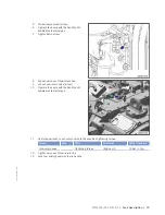
Install fuel line (2).
Note:
Observe the inscription on the union nuts (1, 3).
17.
Tighten union nuts (1, 3) marked with “35 +3 Nm” (see arrows) with torque wrench to the specified
tightening torque.
Name
Size
Type
Lubricant
Value/Standard
Union nut
M14
Tightening torque
(Engine oil)
35 Nm +3 Nm
18.
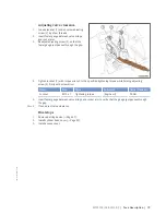
Tighten union nuts (1, 3) marked with “30 +3 Nm” (see arrows) with torque wrench to the specified
tightening torque.
Name
Size
Type
Lubricant
Value/Standard
Union nut
M14
Tightening torque
(Engine oil)
30 Nm +3 Nm
19.
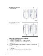
Connect leak-off fuel line to cylinder head.
Final steps
1.
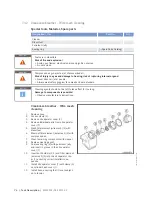
Install cylinder head cover (→ Page 80).
2.
Clean mating faces on cylinder head and charge-air manifold.
3.
Check gaskets for damage and replace them, if required.
4.
Coat gaskets with grease and place onto cylinder head.
5.
Install charge-air pipes.
6.
Install engine governor (→ Page 136).
7.
Open fuel supply line.
8.
Vent fuel system (→ Page 94)
88 | Task Description | MS15018/02E 2013-09
TIM-ID: 0000000023 - 003


