background image

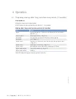
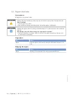
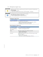
4.6 Emergency engine stop

CAUTION

Shutting down from full-load operation may cause hot water to escape from the expansion tank.

Risk of scalding!

• Allow engine to cool down.
• Wear protective clothing, protective gloves, and safety goggles / safety mask.

NOTICE

An emergency stop causes extreme stress to the engine plant.

Risk of overheating, damage to components!

• Initiate emergency stop only in emergency situations.

Emergency engine stop

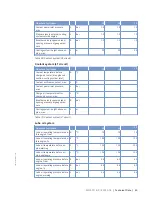
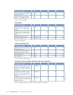
Item

Action

Emergency stop pushbutton Press EMERGENCY STOP pushbutton.

• Engine is stopped by disconnecting the power supply to the ECU;
• Emergency-air shutoff flaps close (if applicable);
• Signalization (e.g. by horn, beacon) is activated.

After emergency engine stop

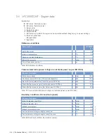
Item

Action

Switch cabinet, operator
station etc. (depending on
manufacturer)

Press pushbutton for alarm acknowledgment.
• Audible and visual signalization stops.

Engine

Manually open emergency-air shutoff flaps (if provided).
• Switch on ECU voltage supply
• Engine is ready for starting.

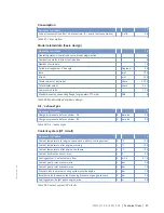
HP system

Energize injectors (for pressure release in HP system using the function
„Blank Shot Afterrun“)
• Switch on ECU voltage supply
• Blank Shots are carried out (requires approx. 20 to 30 s.)

MS150118/01E 2015-05

| Operation | 57

TIM-ID: 0000062460 - 001

Summary of Contents for 12V2000Bx6x

Page 1: ...Operating Instructions Diesel engine 12V2000Gx6x 16V2000Gx6x 18V2000Gx6x 12V2000Bx6x 16V2000Bx6x 18V2000Bx6x MS150118 01E ...

Page 2: ...0 3B continuous operation variable load ICXN 16V2000G26F 56 kW cyl 1500 3B continuous operation variable load ICXN 16V2000G36F 63 kW cyl 1500 3B continuous operation variable load ICXN 18V2000G26F 61 kW cyl 1500 3B continuous operation variable load ICXN Table 1 Overview of validity 2015 Copyright MTU Friedrichshafen GmbH This publication is protected by copyright and may not be used in any way wh...

Page 3: ...ing manually 92 7 1 2 Engine Barring with starting system 93 7 2 Crankcase Breather 94 7 2 1 Crankcase breather Oil mist fine separator replacement 94 7 3 Valve Drive 95 7 3 1 Valve clearance Check and adjustment 95 7 3 2 Cylinder head cover Removal and installation 98 7 4 Injection Valve Injector 99 7 4 1 Injector Replacement 99 7 4 2 Injector Removal and installation 100 7 4 3 Injector functions...

Page 4: ...age Check 140 7 15 2 Coolant level sensor Check 141 7 15 3 Pump capacity Check 142 7 15 4 Coalescer filter element Replacement 143 7 16 Engine Governor 145 7 16 1 Engine control system Overview 145 7 16 2 Engine governor Removal and installation 146 7 16 3 Engine governor plug connections Check 147 7 17 Wiring General for Engine Gearbox Unit 148 7 17 1 Engine cabling Check 148 7 18 Accessories for...

Page 5: ...e with the Spare Parts Catalog MTU contact Service partner In the original as delivered configuration or in a configuration approved by the manufacturer in writ ing including engine control parameters In compliance with all safety regulations and in adherence with all warning notices in this manual With maintenance work performed in accordance with the Maintenance Schedule throughout the useful li...

Page 6: ...ation authorities The manufacturer does not accept any liability for violations of the emission reg ulations The maintenance schedules of the manufacturer must be observed over the entire life cycle of the product Replacing components with emission labels Emission labels are attached to all MTU engines These must remain on the engine throughout its op erational life Engines used exclusively in lan...

Page 7: ...l must be instructed repeatedly Personnel requirements All work on the product shall be carried out by trained and qualified personnel only Training at the Training Center of the manufacturer Technical personnel from the areas mechanical engineering plant construction and electrical engi neering The operator must define the responsibilities of the personnel involved in operation maintenance re pai...

Page 8: ...eight forklift truck Prior to transporting the engine genset system it is imperative to install the transport locking de vice for the crankshaft Prior to transporting the engine genset system it is imperative to install the transport locks for the engine mounts Secure the engine genset system such as to preclude tipping during transport Secure the engine system genset as to preclude slipping and t...

Page 9: ...ne mounts damping elements couplings and V belts must not be painted They may only be installed after painting the engine or must be covered before painting work is carried out The following applies to starters with copper beryllium alloy pinions Wear a respirator mask filter class P3 Do not blow out the interior of the flywheel housing or the starter with compressed air Clean the flywheel housing...

Page 10: ...cable straps Welding work Welding operations on the product or mounted units are not permitted Cover the product when welding in its vicinity Before starting welding work Switch off the power supply master switch Disconnect the battery Separate the electrical ground of electronic equipment from the ground of the unit No other maintenance or repair work must be carried out in the vicinity of the pr...

Page 11: ...hat cabling cannot be dam aged during operation by Contact with sharp edges Chafing on components Contact with hot surfaces Do not secure cables on lines carrying fluids Do not use cable straps to secure cables Always use connector pliers to tighten union nuts on connectors Subject the device as well as the product to a functional testing on completion of all repair work In particular check the fu...

Page 12: ... with its handling Noise Noise can lead to an increased risk of accidents if acoustic signals warning shouts or sounds indicating danger are drowned Wear ear protectors in workplaces with a sound pressure level in excess of 85 dB A Environmental protection and disposal Dispose of used fluids lubricants and filters in accordance with local regulations Within the EU batteries can be returned free of...

Page 13: ...test in accordance with the specifications Painting Observe the relevant safety data sheet for all materials When carrying out painting work outside the spray stands provided with fume extraction systems ensure that the area is well ventilated Make sure that neighboring work areas are not adversely af fected There must be no naked flames in the vicinity No smoking Observe fire prevention regulatio...

Page 14: ...emedial action NOTICE In the event of a situation involving potentially adverse effects on the product Consequences Material damage Remedial action Additional product information Safety notices 1 This manual with all safety instructions and safety notices must be issued to all personnel involved in operation maintenance repair or transportation 2 The higher level warning notice is used if several ...

Page 15: ...gnated in accordance with DIN ISO 1204 as viewed from driving end 4 For cylinder designation in accordance with DIN ISO 1204 the letter Ax refers to the cylinders on the left hand side of the engine 1 and letter Bx refers to the cylinders on the right hand side 3 The cylinders of each bank are numbered consecutively starting with x 1 at driving end 4 The numbering of other engine components also s...

Page 16: ...and regulation system 4 Charge air line 5 Belt drive 6 Engine coolant pump 7 Fuel system low pressure 8 Fuel filter 9 Exhaust turbocharger 10 Fuel system high pres sure 11 Charge air line 12 Starting equipment 13 PTO system driving end KS Driving end 16 General Information MS150118 01E 2015 05 TIM ID 0000053439 002 ...

Page 17: ... and regulation system 4 Charge air line 5 Belt drive 6 Engine coolant pump 7 Fuel system low pressure 8 Fuel filter 9 Exhaust turbocharger 10 Fuel system high pres sure 11 Charge air line 12 PTO system driving end KS Driving end MS150118 01E 2015 05 General Information 17 TIM ID 0000053439 002 ...

Page 18: ...s sure 11 Charge air line 12 Starting equipment 13 PTO system driving end KS Driving end Key to engine model designation 12 16 18 Number of cylinders V Cylinder arrangement Vee engine 2000 Series B G Application G for peripheral energy systems engineering B for base load x Application segment 0 1 2 9 6 Design index 0 1 2 9 F Additional feature F 50 Hz Table 2 Key to engine model designation 18 Gen...

Page 19: ...itions Power related data power ratings are net brake power as per ISO 3046 Number of cylinders 12 16 18 Rated engine speed A rpm 1500 1500 1500 Continuous power ISO 3046 10 overload capability A kW 665 709 887 Net brake power without fan fuel stop power ISO 3046 A kW 732 780 976 Mean effective pressure pme continuous power ISO 3046 bar 19 9 15 9 17 7 Mean effective pressure pme fuel stop power IS...

Page 20: ...n X X X Combustion method direct fuel in jection X X X Number of cylinders 12 16 18 Cylinder arrangement Vee angle Degrees 90 90 90 Bore mm 135 135 135 Stroke mm 156 156 156 Displacement of a cylinder Liters 2 333 2 233 2 233 Total displacement Liters 26 8 35 7 40 2 Compression ratio 17 50 17 5 17 5 Standard housing connecting flange engine main PTO side SAE 0 0 0 Table 7 Model related data basic ...

Page 21: ...auge pres sure R bar 1 0 1 0 1 0 Cooling system height above en gine max L m 20 20 20 Table 9 Coolant system HT circuit Coolant system LT circuit Number of cylinders 12 16 18 Coolant temperature before charge air cooler at engine con nection cooling system inlet A C Coolant antifreeze content max L Coolant pump inlet pressure max L bar Charge air temperature after charge air cooler max L C Breathe...

Page 22: ... 11 Lube oil system Fuel system Number of cylinders 12 16 18 Fuel pressure at engine supply connection min during engine start L bar 0 5 0 5 0 5 Fuel pressure at engine supply connection max during engine start bar 0 5 0 5 0 5 Fuel supply flow rate max A Liters min 30 30 30 Fuel return volume max A Liters min 30 30 30 Table 12 Fuel system General operating data Number of cylinders 12 16 18 Coolant...

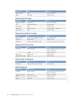
Page 23: ... system R Liters 63 70 73 Charge air coolant engine side R Liters Fuel engine side R Liters 6 6 7 Engine oil capacity initial filling standard oil system option max operating inclination positions R Liters 92 114 122 Oil change quantity max standard oil system option max operating inclination positions R Liters 80 102 110 Table 15 Capacities Fan fan cooler Number of cylinders 12 16 18 Fan push typ...

Page 24: ...ree field sound power level Lp 1 m distance ISO 6798 2 dB A tol erance R dB A 100 102 101 Engine surface noise with attenu ated intake noise filter DL sound power level LW ISO 6798 2 db A tolerance R dB A 118 119 119 Table 17 Sound 24 Technical Data MS150118 01E 2015 05 TIM ID 0000053440 002 ...

Page 25: ...Reference conditions Power related data power ratings are net brake power as per ISO 3046 Number of cylinders 12 16 18 Rated engine speed A rpm 1500 1500 1500 Continuous power ISO 3046 10 overload capability A kW 709 890 1102 Net brake power without fan fuel stop power ISO 3046 A kW 780 979 1212 Mean effective pressure pme continuous power ISO 3046 bar 21 2 19 9 21 9 Mean effective pressure pme fu...

Page 26: ...on X X X Combustion method direct fuel in jection X X X Number of cylinders 12 16 18 Cylinder arrangement Vee angle Degrees 90 90 90 Bore mm 135 135 135 Stroke mm 156 156 156 Displacement of a cylinder Liters 2 233 2 233 2 233 Total displacement Liters 26 8 35 7 40 2 Compression ratio 17 50 17 5 17 5 Standard housing connecting flange engine main PTO side SAE 0 0 0 Table 22 Model related data basi...

Page 27: ...uge pres sure R bar 1 0 1 0 1 0 Cooling system height above en gine max L m 20 20 20 Table 24 Coolant system HT circuit Coolant system LT circuit Number of cylinders 12 16 18 Coolant temperature before charge air cooler at engine con nection cooling system inlet A C Coolant antifreeze content max L Coolant pump inlet pressure max L bar Charge air temperature after charge air cooler max L C Breathe...

Page 28: ... 26 Lube oil system Fuel system Number of cylinders 12 16 18 Fuel pressure at engine supply connection min during engine start L bar 0 5 0 5 0 5 Fuel pressure at engine supply connection max during engine start bar 0 5 0 5 0 5 Fuel supply flow rate max A Liters min 30 30 30 Fuel return volume max A Liters min 30 30 30 Table 27 Fuel system General operating data Number of cylinders 12 16 18 Coolant...

Page 29: ...ling system R Liters 63 70 73 Charge air coolant engine side R Liters Fuel engine side R Liters 6 6 7 Engine oil capacity initial filling standard oil system option max operating inclination positions R Liters 92 114 122 Oil change quantity max standard oil system option max operating inclination positions R Liters 80 102 110 Table 30 Capacities Fan fan cooler Number of cylinders 12 16 18 Fan push...

Page 30: ...DL free field sound power level Lp 1 m distance ISO 6798 2 dB A tol erance R dB A 100 103 Engine surface noise with attenu ated intake noise filter DL sound power level LW ISO 6798 2 db A tolerance R dB A 118 121 Table 32 Sound 30 Technical Data MS150118 01E 2015 05 TIM ID 0000054516 002 ...

Page 31: ...Reference conditions Power related data power ratings are net brake power as per ISO 3046 Number of cylinders 12 16 18 Rated engine speed A rpm 1800 1800 1800 Continuous power ISO 3046 10 overload capability A kW 716 998 1097 Net brake power without fan fuel stop power ISO 3046 A kW 789 1098 1207 Mean effective pressure pme continuous power ISO 3046 bar 17 8 18 6 18 2 Mean effective pressure pme f...

Page 32: ...n X X X Combustion method direct fuel in jection X X X Number of cylinders 12 16 18 Cylinder arrangement Vee angle Degrees 90 90 90 Bore mm 135 135 135 Stroke mm 156 156 156 Displacement of a cylinder Liters 2 233 2 233 2 233 Total displacement Liters 26 8 35 7 40 2 Compression ratio 17 50 17 5 17 5 Standard housing connecting flange engine main PTO side SAE 0 0 0 Table 37 Model related data basic...

Page 33: ...uge pres sure R bar 1 0 1 0 1 0 Cooling system height above en gine max L m 20 20 20 Table 39 Coolant system HT circuit Coolant system LT circuit Number of cylinders 12 16 18 Coolant temperature before charge air cooler at engine con nection cooling system inlet A C Coolant antifreeze content max L Coolant pump inlet pressure max L bar Charge air temperature after charge air cooler max L C Breathe...

Page 34: ...e 41 Lube oil system Fuel system Number of cylinders 12 16 18 Fuel pressure at engine supply connection min during engine start L bar 0 5 0 5 0 5 Fuel pressure at engine supply connection max during engine start bar 0 5 0 5 0 5 Fuel supply flow rate max A Liters min 30 30 30 Fuel return volume max A Liters min 30 30 30 Table 42 Fuel system General operating data Number of cylinders 12 16 18 Coolan...

Page 35: ... system R Liters 63 70 73 Charge air coolant engine side R Liters Fuel engine side R Liters 6 6 7 Engine oil capacity initial filling standard oil system design max operating inclination positions R Liters 92 114 122 Oil change quantity max standard oil system design max operating inclination positions R Liters 80 102 110 Table 45 Capacities Fan fan cooler Number of cylinders 12 16 18 Fan push typ...

Page 36: ...ree field sound power level Lp 1 m distance ISO 6798 2 dB A tol erance R dB A 101 101 103 Engine surface noise with attenu ated intake noise filter DL sound power level LW ISO 6798 2 db A tolerance R dB A 119 118 121 Table 47 Sound 36 Technical Data MS150118 01E 2015 05 TIM ID 0000054519 002 ...

Page 37: ...of cylinders 12 16 Rated engine speed A rpm 1500 1500 Continuous power ISO 3046 10 overload capability A kW 665 806 Net brake power without fan fuel stop power ISO 3046 A kW 732 887 Mean effective pressure pme continuous power ISO 3046 bar 19 9 18 1 Mean effective pressure pme fuel stop power ISO 3046 bar 21 8 19 9 Table 49 Power related data power ratings are net brake power as per ISO 3046 Bound...

Page 38: ... 12 16 Charge air pressure before cylinder DL R bar abs 2 9 2 6 Charge air pressure before cylinder BL R bar abs 3 2 2 8 Table 53 Air exhaust gas Coolant system HT circuit Number of cylinders 12 16 Coolant temperature at engine connection outlet to cooling sys tem A C 100 100 Coolant temperature after engine warning L C 102 102 Coolant temperature after engine shutdown L C 105 105 Coolant antifree...

Page 39: ...5 105 Lube oil operating pressure before engine from R bar 5 8 6 2 Lube oil operating pressure before engine to R bar 8 5 8 8 Lube oil operating pressure before engine warning L bar 4 5 4 5 Lube oil operating pressure before engine shutdown L bar 4 0 4 0 Lube oil microfilter main flow number of cartridges per unit 2 3 Table 56 Lube oil system Fuel system Number of cylinders 12 16 Fuel pressure at ...

Page 40: ...side R Liters 6 6 Engine oil capacity initial filling standard oil system option max operating inclination positions R Liters 92 114 Oil change quantity max standard oil system option max oper ating inclination positions R Liters 80 102 Table 60 Capacities Fan fan cooler Number of cylinders 12 16 Fan push type X X Fan drive mechanical via V belt X X Table 61 Fan fan cooler Sound Number of cylinder...

Page 41: ...rs 12 16 18 Rated engine speed A rpm 1500 1500 1500 Continuous power ISO 3046 10 overload capability A kW 709 890 1102 Net brake power without fan fuel stop power ISO 3046 A kW 780 979 1212 Mean effective pressure pme continuous power ISO 3046 bar 21 2 19 9 21 9 Mean effective pressure pme fuel stop power ISO 3046 bar 23 3 21 9 24 1 Table 64 Power related data power ratings are net brake power as ...

Page 42: ... 5 Standard housing connecting flange engine main PTO side SAE 0 0 0 Table 67 Model related data basic design Air exhaust gas Number of cylinders 12 16 18 Charge air pressure before cylin der DL R bar abs 2 8 2 8 3 4 Charge air pressure before cylin der BL R bar abs 3 1 3 1 3 7 Table 68 Air exhaust gas Coolant system HT circuit Number of cylinders 12 16 18 Coolant temperature at engine connection ...

Page 43: ... air temperature after charge air cooler max L C Breather valve expansion tank opening pressure at gauge pres sure R bar Cooling system height above en gine max L m Table 70 Coolant system LT circuit Lube oil system Number of cylinders 12 16 18 Lube oil operating temperature be fore engine from R C 75 75 75 Lube oil operating temperature be fore engine to R C 100 100 100 Lube oil temperature befor...

Page 44: ...eating preheating temperature min L C 32 32 32 Starting is blocked if the engine coolant temperature is below C 20 20 20 Firing speed from R rpm 100 100 100 Firing speed to R rpm 120 120 120 Table 73 General operating data Inclined positions standard oil system reference waterline Number of cylinders 12 16 18 Longitudinal inclination continu ous max driving end bottom op tion max operating inclina...

Page 45: ...h type X X X Fan drive mechanical via V belt X X X Table 76 Fan fan cooler Sound Number of cylinders 12 16 18 Exhaust noise not attenuated DL free field sound pressure level Lp 1 m distance ISO 6798 3 dB A tolerance R dB A 112 113 115 Exhaust noise not attenuated DL sound power level LW ISO 6798 3 dB A tolerance R dB A 124 126 128 Engine surface noise with attenu ated intake noise filter DL free f...

Page 46: ...umber of cylinders 16 Rated engine speed A rpm 1500 Continuous power ISO 3046 10 overload capability A kW 1000 Net brake power without fan fuel stop power ISO 3046 A kW 1100 Mean effective pressure pme continuous power ISO 3046 bar 22 4 Mean effective pressure pme fuel stop power ISO 3046 bar 24 6 Table 79 Power related data power ratings are net brake power as per ISO 3046 Boundary conditions for...

Page 47: ...ders 16 Charge air pressure before cylinder DL R bar abs 3 2 Charge air pressure before cylinder BL R bar abs 3 5 Table 83 Air exhaust gas Coolant system HT circuit Number of cylinders 16 Coolant temperature at engine connection outlet to cooling system A C 100 Coolant temperature after engine warning L C 102 Coolant temperature after engine shutdown L C 105 Coolant antifreeze content max L 50 Coo...

Page 48: ...re before engine from R bar 6 2 Lube oil operating pressure before engine to R bar 8 8 Lube oil operating pressure before engine warning L bar 4 5 Lube oil operating pressure before engine shutdown L bar 4 0 Lube oil microfilter main flow number of cartridges per unit 3 Table 86 Lube oil system Fuel system Number of cylinders 16 Fuel pressure at engine supply connection min during engine start L b...

Page 49: ...tandard oil system option max operat ing inclination positions R Liters 114 Oil change quantity max standard oil system option max operating in clination positions R Liters 102 Table 90 Capacities Fan fan cooler Number of cylinders 16 Fan push type X Fan drive mechanical via V belt X Table 91 Fan fan cooler Sound Number of cylinders 16 Exhaust noise not attenuated DL free field sound pressure leve...

Page 50: ... of cylinders Firing order 12V A1 B5 A5 B3 A3 B6 A6 B2 A2 B4 A4 B1 16V A1 B5 A3 A5 B2 B8 A2 A8 B3 A7 B4 B6 A4 A6 B1 B7 18V A1 B6 A3 B4 A5 B2 A7 B1 A9 B3 A8 B5 A6 B7 A4 B9 A2 B8 50 Technical Data MS150118 01E 2015 05 TIM ID 0000053446 002 ...

Page 51: ...m approx 1421 mm 12V2000G26F approx 2044 mm approx 1522 mm approx 1470 mm 16V2000G26F approx 2394 mm approx 1570 mm approx 1421 mm 18V2000G26F approx 2569 mm approx 1572 mm approx 1421 mm 16V2000G36F approx 2394 mm approx 1570 mm approx 1421 mm 12V2000B76switchable approx 2044 mm approx 1522 mm approx 1470 mm 16V2000B76switchable approx 2394 mm approx 1570 mm approx 1421 mm 18V2000B76switchable ap...

Page 52: ...eck engine oil level Page 121 Fuel system Use appropriate equipment to fill system via fuel supply line Fuel system Vent Page 107 Coolant circuit If engine is out of service for more than one year change engine coolant Page 127 Coolant circuit Check engine coolant level Page 126 Coolant circuit Preheat engine coolant with coolant preheating unit if fitted Engine control system Check plug connectio...

Page 53: ...oil system Check engine oil level Page 121 Coolant circuit Check engine coolant level Page 126 Coolant circuit Preheat engine coolant with coolant preheating unit if fitted Fuel prefilter if fitted Drain water see manufacturer s documentation Engine control system Switch on Table 95 Startup MS150118 01E 2015 05 Operation 53 TIM ID 0000054738 001 ...

Page 54: ...ing the engine with starter system make sure that there are no persons in the en gine s danger zone WARNING High level of engine noise when the engine is running Risk of damage to hearing Wear ear protectors Starting the engine Item Measure Engine Start the engine documentation of the vehicle manufacturer plant manu facturer 54 Operation MS150118 01E 2015 05 TIM ID 0000010107 006 ...

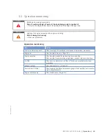
Page 55: ... of operational data speed temperature pressures Engine oil Check engine oil level Page 121 Engine operation Check engine visually for leaks and general condition Check engine for abnormal running noises exhaust color and vibrations Air filter Check service indicator at air filter if fitted see manufacturer s docu mentation Exhaust system Check exhaust color Page 61 Fuel prefilter if fitted Check ...

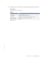
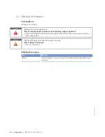
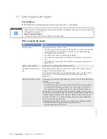
Page 56: ... running at full load subjects it to extreme thermal and mechanical stresses Overheating of and therefore damage to components is possible Before shutting down the engine allow it to idle until the engine temperatures decrease and constant levels are indicated Preparation Item Action Engine Allow the engine to cool down by running it at idle speed for approx 5 mi nutes Stopping the engine Item Act...

Page 57: ...ngine is stopped by disconnecting the power supply to the ECU Emergency air shutoff flaps close if applicable Signalization e g by horn beacon is activated After emergency engine stop Item Action Switch cabinet operator station etc depending on manufacturer Press pushbutton for alarm acknowledgment Audible and visual signalization stops Engine Manually open emergency air shutoff flaps if provided ...

Page 58: ...of service for longer than 1 week seal the engine on the air and exhaust side If the engine is to be taken out of service for longer than 1 month it has to be preserved MTU Preservation and Represervation Instructions A001070 HP system injector noise The pressure is released in the system by means of the function Blank Shot Afterrun Injectors are energized A small injection quantity is diverted in...

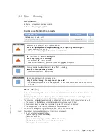
Page 59: ...rectly at seals or electronic components such as connectors or ECUs Plant Cleaning 1 Carry out plant cleaning only in areas where an appropriate oil separator is provided environmental protection 2 Prior to putting the cleaning unit into operation read the operating instructions of the high pressure cleaning units carefully and observe the safety precautions 3 The following requirements apply for ...

Page 60: ...e 133 Page 134 Page 137 W1005 Replace air filter Page 115 W1006 Replace fuel injectors Page 99 W1008 Replace engine oil filter when changing engine oil or when the limit value years is reached at the latest Page 123 W1009 X Check layer thickness of the oil residue clean and replace filter sleeve no later than with every engine oil change Page 124 W1055 Replace oil separator Page 94 W1178 Replace p...

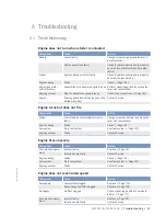
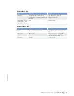
Page 61: ...re Component Cause Action Starter Poor rotation by starter Battery low or faulty Charge or replace battery see manufac turer s documentation Engine cabling Faulty Check Page 148 Fuel system Air in fuel system Vent fuel system Page 107 Engine governor Faulty Contact Service Engine fires unevenly Component Cause Action Fuel injection equip ment Injector faulty Replace Page 99 Injection pump faulty C...

Page 62: ...take temperature too high Check fans and intake exhaust lines Charge air pressure too low Component Cause Action Air supply Air filter clogged Check signal ring position of service in dicator Page 117 Leaking Replace seals nuts Intercooler Contaminated Contact Service Exhaust turbocharger Faulty Contact Service Coolant leaks at intercooler Component Cause Action Intercooler Leaking major coolant d...

Page 63: ...turbocharger cylinder head piston rings cylinder liner Faulty Contact Service White exhaust gas Component Cause Action Engine Not at operating temperature Run engine to reach operating tempera ture Fuel system Water in fuel Check fuel system at fuel prefilter Drain fuel prefilter Page 111 Intercooler Leaking Contact Service MS150118 01E 2015 05 Troubleshooting 63 TIM ID 0000051898 002 ...

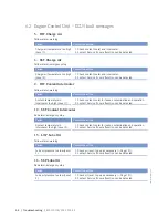
Page 64: ...for leaks contamination and operation 2 Contact Service if no malfunction can be detected 10 SS T Coolant Intercooler Red alarm emergency stop Cause Corrective action Coolant temperature in intercooler too high Level 2 1 Check coolant cooler for leaks contamination and operation 2 Contact Service if no malfunction can be detected 15 LO P Lube Oil Yellow alarm warning Cause Corrective action Lube o...

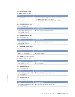
Page 65: ...il pressure at oil filter too high Level 2 u Check oil filter replace as necessary 27 HI Leak Fuel Level Yellow alarm warning Cause Corrective action Leak fuel level too high u Contact Service 30 SS Engine Overspeed Red alarm emergency stop Cause Corrective action Engine speed too high u Restart engine 33 HI P Diff Fuel Yellow alarm warning Cause Corrective action Differential pressure at fuel fil...

Page 66: ...on can be detected 52 SS T Lube Oil Red alarm emergency stop Cause Corrective action Lube oil temperature too high Level 2 1 Check cooling system 2 Contact Service if no malfunction can be detected 53 HI T Intake Air Yellow alarm warning Cause Corrective action Intake air temperature too high Level 1 u 54 HIHI T Intake Air Yellow alarm warning Cause Corrective action Intake air temperature too hig...

Page 67: ...ing system 2 Contact Service if no malfunction can be detected 68 SS T Coolant Red alarm emergency stop 3 min delay Cause Corrective action Coolant temperature too high Level 2 1 Check cooling system 2 Contact Service if no malfunction can be detected 81 AL Rail Leakage Yellow alarm warning Cause Corrective action Rail pressure gradient too low for start or too high for stop HP fuel system leaky a...

Page 68: ... 2 Observe additional messages 91 SS Release Speed Not Reached Yellow alarm warning Cause Corrective action Run up speed not reached start aborted 1 Restart engine Page 54 2 Observe additional messages 92 SS Starter Speed Mot Reached Yellow alarm warning Cause Corrective action Starter speed not reached termination of starting sequence starter does not turn or turns slowly 1 Check battery 2 Check ...

Page 69: ...ounter Defect Yellow alarm warning Cause Corrective action Hour meter faulty u Replace Engine Control Unit at next opportunity 118 LO ECU Supply Voltage Yellow alarm warning Cause Corrective action Supply voltage too low Level 1 u Check batteries charge as necessary check alternator 119 LOLO ECU Power Supply Voltage Yellow alarm warning Cause Corrective action Supply voltage too low Level 2 u Chec...

Page 70: ...peration has exceeded the set maximum value u 180 AL CAN1 Node Lost Yellow alarm warning Cause Corrective action Connection to a node on CAN bus 1 failed 1 Check devices connected to CAN 2 Check wiring termination resistor installed 181 AL CAN2 Node Lost Yellow alarm warning Cause Corrective action Connection to a node on CAN bus 2 failed 1 Check devices connected to CAN 2 Check wiring termination...

Page 71: ...n CAN controller 1 is in Bus Off status 1 Check CAN bus for short circuit rectify short circuit as necessary 2 Check shielding improve shielding as necessary 3 Contact Service 187 AL CAN1 Error Passive Yellow alarm warning Cause Corrective action CAN controller 1 has signaled a warning 1 Check CAN bus for short circuit rectify short circuit as necessary 2 Check shielding improve shielding as neces...

Page 72: ... action Charge air temperature sensor faulty u Check sensor B9 and wiring replace as necessary Page 148 205 SD T Coolant Intercooler Yellow alarm warning Cause Corrective action Coolant pressure sensor of intercooler faulty u Check sensor B26 and wiring replace as necessary Page 148 208 SD P Charge Air Yellow alarm warning Cause Corrective action Charge air pressure sensor faulty u Check sensor B1...

Page 73: ... B3 and wiring replace as necessary Page 148 220 SD Level Coolant Water Yellow alarm warning Cause Corrective action Coolant level sensor faulty 1 Check sensor F33 and wiring replace as necessary Page 148 2 Fault is rectified when electronics are switched back on 221 SD P Diff Lube Oil Yellow alarm warning Cause Corrective action Lube oil differential pressure sensor faulty u Check sensor B5 1 and...

Page 74: ...ensor Defect Red alarm emergency stop Cause Corrective action Engine stop due to camshaft sensor fault and a previous crankshaft sensor fault in the same operating cycle 1 Check sensor and wiring to connectors B1 and B13 replace as necessary Page 148 2 Acknowledge alarm 3 Restart engine Page 54 230 SD Crankshaft Speed Yellow alarm warning Cause Corrective action Crankshaft sensor faulty 1 Check se...

Page 75: ...ng Yellow alarm warning Cause Corrective action Analog speed setting faulty 1 Check speed setting transmitter and wiring replace as necessary Page 148 2 Fault is rectified when engine is restarted 269 SD Loadp Analog fil Yellow alarm warning Cause Corrective action The filtered analog signal from the load pulse is not present 1 Check wiring replace as necessary 2 Fault is rectified when engine is ...

Page 76: ...cuit in cylinder A3 injector wiring Result Misfiring 1 Check injector wiring 2 Rectify injector solenoid valve short circuit positive to negative e g by exchanging injectors 3 Fault is rectified when engine is restarted 324 AL Wiring Cylinder A4 Yellow alarm warning Cause Corrective action Short circuit in cylinder A4 injector wiring Result Misfiring 1 Check injector wiring 2 Rectify injector sole...

Page 77: ...cuit in cylinder A8 injector wiring Result Misfiring 1 Check injector wiring 2 Rectify injector solenoid valve short circuit positive to negative e g by exchanging injectors 3 Fault is rectified when engine is restarted 329 AL Wiring Cylinder A9 Yellow alarm warning Cause Corrective action Short circuit in cylinder A9 injector wiring Result Misfiring 1 Check injector wiring 2 Rectify injector sole...

Page 78: ...cuit in cylinder B4 injector wiring Result Misfiring 1 Check injector wiring 2 Rectify injector solenoid valve short circuit positive to negative e g by exchanging injectors 3 Fault is rectified when engine is restarted 335 AL Wiring Cylinder B5 Yellow alarm warning Cause Corrective action Short circuit in cylinder B5 injector wiring Result Misfiring 1 Check injector wiring 2 Rectify injector sole...

Page 79: ...valve short circuit positive to negative e g by exchanging injectors 3 Fault is rectified when engine is restarted 341 AL Open Load Cylinder A1 Yellow alarm warning Cause Corrective action Open circuit in cylinder A1 injector wiring Result Misfiring 1 Check injector wiring exclude disruption in solenoid valve e g by injector replacement 2 Fault is rectified after each working cycle 342 AL Open Loa...

Page 80: ...by injector replacement 2 Fault is rectified after each working cycle 347 AL Open Load Cylinder A7 Yellow alarm warning Cause Corrective action Open circuit in cylinder A7 injector wiring Result Misfiring 1 Check injector wiring exclude disruption in solenoid valve e g by injector replacement 2 Fault is rectified after each working cycle 348 AL Open Load Cylinder A8 Yellow alarm warning Cause Corr...

Page 81: ...by injector replacement 2 Fault is rectified after each working cycle 354 AL Open Load Cylinder B4 Yellow alarm warning Cause Corrective action Open circuit in cylinder B4 injector wiring Result Misfiring 1 Check injector wiring exclude disruption in solenoid valve e g by injector replacement 2 Fault is rectified after each working cycle 355 AL Open Load Cylinder B5 Yellow alarm warning Cause Corr...

Page 82: ... rectified after each working cycle 361 AL Injector Power Stage Low Yellow alarm warning Cause Corrective action Internal electronic fault electronics possibly faulty 1 Start Engine Control Unit self test 2 Replace ECU in case of fault if self test diagnoses Electronics OK check for additional fault messages e g wiring fault 362 AL Injector Power Stage High Yellow alarm warning Cause Corrective ac...

Page 83: ...cuit or wire break on transistor output 2 plant side TOP 2 u Check wiring Page 148 383 AL Wiring TOP 3 Yellow alarm warning Cause Corrective action Short circuit or wire break on transistor output 3 plant side TOP 3 u Check wiring Page 148 384 AL Wiring TOP 4 Yellow alarm warning Cause Corrective action Short circuit or wire break on transistor output 4 plant side TOP 4 u Check wiring Page 148 390...

Page 84: ...ive action Line disruption at digital input 4 u Check wiring Page 148 404 AL Open Load Digital Input 5 Yellow alarm warning Cause Corrective action Line disruption at digital input 5 u Check wiring Page 148 405 AL Open Load Digital Input 6 Yellow alarm warning Cause Corrective action Line disruption at digital input 6 u Check wiring Page 148 406 AL Open Load Digital Input 7 Yellow alarm warning Ca...

Page 85: ...tive action Injector voltage too high Level 1 u Perform Engine Control Unit self test replace as necessary 413 HIHI U PDU Yellow alarm warning Cause Corrective action Injector voltage too high Level 2 u Perform Engine Control Unit self test replace as necessary 414 HI Level Water Fuel Prefilter Yellow alarm warning Cause Corrective action Water level in fuel prefilter too high u Empty fuel prefilt...

Page 86: ...HP fuel system u Contact Service 439 HI P Fuel 2 Common Rail Yellow alarm warning Cause Corrective action Rail pressure above specified value HP fuel control block jamming or wiring faulty 1 Check wiring of HP fuel control block 2 Contact Service if no malfunction can be detected 441 AL System 2 Leaky Yellow alarm warning Cause Corrective action Pressure gradient in rail is too low during starting...

Page 87: ... Restart engine Page 54 454 SS Power Reduction Active Yellow alarm warning Cause Corrective action Power reduction activated u Observe any other messages 470 SD T ECU Yellow alarm warning Cause Corrective action Temperature sensor for Engine Control Unit faulty u Replace Engine Control Unit at next opportunity 471 SD HP fuel control block Yellow alarm warning Cause Corrective action Actuation of H...

Page 88: ...alarm warning Cause Corrective action Combined alarm initiated by plant red u Observe any other fault messages 480 AL Ext Engine Protection Yellow alarm warning Cause Corrective action External engine protection function active u Contact Service 514 Write Error Flash Yellow alarm warning Cause Corrective action Value was not accepted into flash u Contact Service 536 AL Wiring PWM_CM1 Yellow alarm ...

Page 89: ...arm warning Cause Corrective action Wire break or short circuit on channel PWM_CM2 u Check wiring to connected device or check connected device actuator sensor replace as necessary 582 AL Emergency Stop Failure Entered in fault memory only Cause Corrective action Emergency stop command was not executed u Contact Service 596 AL Cons Parameter Record Yellow alarm warning Cause Corrective action Stan...

Page 90: ...ction module as reaction to faulty or manipulated EIL u Replace EIL 616 AL EIL Error Yellow alarm warning Cause Corrective action Alarm with faulty or manipulated EIL u Replace EIL 762 AL Smart Connect Lost Yellow alarm warning Cause Corrective action Smart Connect device has failed on CAN bus u Check wiring or Smart Connect replace as necessary 832 AL EIL Engine Number Differs Yellow alarm warnin...

Page 91: ...ating LSI channels u Contact Service 973 AL Checksum IIG Yellow alarm warning Cause Corrective action Checksum calculation or word limit check for one of the injectors is not correct u Contact Service 1130 AL Short Circuit Analog Output 1 Yellow alarm warning Cause Corrective action The value output at analog output 1 deviates excessively from the value read back u Check wiring 1131 AL Short Circu...

Page 92: ...ll safety devices are put back in place and all tools are removed from the engine Cranking engine manually later al installation 1 Remove starting equipment from flywheel housing Page 119 2 Engage barring tool 2 with ring gear and install on flywheel housing 3 Apply ratchet 1 to barring tool 2 4 Rotate crankshaft in engine direction of ro tation Apart from the normal compression resistance there s...

Page 93: ...fore cranking the engine with starter system make sure that there are no persons in the en gine s danger zone Barring engine with starting system 1 If fitted press pushbutton Bar engine without starting and keep depressed 2 Let the crankshaft rotate until oil pressure is indicated but not longer than 10 seconds 3 Repeat procedure after about 20 seconds if necessary MS150118 01E 2015 05 Task Descri...

Page 94: ...bustion residues which are harmful to health Risk of injury and poisoning Wear protective clothing gloves and goggles safety mask Avoid contact with skin Do not inhale oil vapor Replacing oil mist fine separator 1 Unscrew screws 1 and remove together with washers 2 and retainer 3 2 Replace oil mist fine separator 4 3 Replace O ring 5 if necessary 4 Screw in screws 1 with washers 2 and retainer 3 5...

Page 95: ...position without marking on flywheel Note With cylinder head and valve gear installed 1 Insert preloaded dial gauge 2 into meas uring device 4 and clamp using screw 1 2 Install measuring device 4 in cylinder head and secure using knurled screw 3 3 Zero dial gauge 2 4 Turn engine using barring device until pis ton A1 reaches firing TDC Result The piston is at firing TDC when both rock er arms are u...

Page 96: ...Side B I X I I X X Overlap TDC in cylinder A1 Side A X I X I I X Side B X I X I X I 16V Firing TDC in cylinder A1 Side A I X X X I X I Side B I X I I X I I X X Overlap TDC in cylinder A1 Side A I I X I X I X I X Side B X I I X X X I 18V Firing TDC in cylinder A1 Side A I X I X I X X Side B X X I X I X I I X I Overlap TDC in cylinder A1 Side A X I X I I X I I X I X Side B I I I X I X X X I Inlet In...

Page 97: ...the specified tightening torque holding the adjusting screw 2 with Allen key to prevent it from turning Name Size Type Lubricant Value Standard Locknut M12x1 Tightening torque 50 Nm 5 Nm 5 Insert feeler gauge between valve bridge and rocker arm to verify that the gauge just passes through the gap Result If not adjust valve clearance Final steps 1 Remove barring device 2 Install cylinder head cover...

Page 98: ... injec tor clamps and remove spade lugs 1 Remove cylinder head cover 2 with gas ket 1 from cylinder head 2 Clean mating face 3 Check condition of gasket 1 in cylinder head cover 2 4 Replace gasket 1 if damaged 5 Place gasket 1 in correct position on cyl inder head 6 Push spade lugs under the terminals on the injector and tighten with torque wrench to the specified tightening torque Name Size Type ...

Page 99: ...ial tools Material Spare parts Designation Use Part No Qty Injector Spare Parts Catalog Screw for hold down clamp Spare Parts Catalog Replacing injector u Remove injector and install new one Page 100 MS150118 01E 2015 05 Task Description 99 TIM ID 0000053453 001 ...

Page 100: ...and safety glasses facial protection WARNING Residual pressure in HP fuel system Risk of injury due to fuel escaping at high pressure Energize the Engine Control Unit for around 30 s after emergency stop or engine stall Wear protective gloves and goggles safety mask Slowly open straight unions WARNING Internal tension and residual pressure in the HP fuel system Parts can be ejected when loosening ...

Page 101: ...fenders Preparatory steps 1 Shut off fuel supply line 2 Drain fuel Page 108 3 Remove cylinder head cover Page 98 Removing injector 1 Remove HP fuel line 1 2 Unscrew union nut 2 3 Pull off pressure pipe neck 3 4 Extract fuel from the exposed bores using the suction device 5 Disconnect terminals arrowed on injector and pull out cable lugs 6 Remove gasket MS150118 01E 2015 05 Task Description 101 TIM...

Page 102: ...ctor 1 into the cylinder head 4 Align faces on injector 1 for mounting in the hold down clamp 2 and insert injector by hand in a straight line into the cylinder head 5 Fit hold down clamp 2 in correct position by hand Installation without press fitting tool 1 Screw in screw 3 and tighten screw 3 to carefully push injector 1 into cylinder head Name Size Type Lubricant Value Standard Screw M8 Preloa...

Page 103: ...3 up to contact point on sealing ring in cylinder head 6 Press pressure pipe neck 3 in completely by hand 7 Align HP connection of injector with pres sure pipe neck 3 8 Coat thread and shoulder of union nut 2 with engine oil and tighten to specified torque using a torque wrench Name Size Type Lubricant Value Standard Retaining screw M24 Preload torque Engine oil 15 Nm 5 Nm 9 Tighten screw 3 for ho...

Page 104: ... HP fuel system Name Size Type Lubricant Value Standard Union nut M20 Tightening torque Engine oil 37 Nm 3 Nm b In case of double wall jacketed HP fuel system Name Size Type Lubricant Value Standard Union nut M20 Tightening torque Engine oil 50 Nm 5 Nm 4 If the fuel system is jacketed tighten retaining screw of HP fuel line 1 on pressure pipe neck 3 to specified tightening torque using torque wren...

Page 105: ...gine oil 37 Nm 3 Nm 2 Push cable lugs under the terminals arrowed on the injector and tighten to specified torque using a torque wrench Name Size Type Lubricant Value Standard Nut M4 Tightening torque Engine oil 1 5 Nm 0 25 Nm Final steps 1 Install cylinder head cover Page 98 2 Open fuel supply line 3 Vent fuel system Page 107 MS150118 01E 2015 05 Task Description 105 TIM ID 0000050909 004 ...

Page 106: ...er successful installation of DiaSys document can be found here C DiaSys Doku auf ihrem Serv ice PC 1 Dialog system DiaSys E531920 2 If no DiaSys is available contact Service Entering injector coding IIG Note After successful installation of DiaSys document can be found here C DiaSys Doku auf ihrem Serv ice PC 1 Dialog system DiaSys E531920 2 If no DiaSys is available contact Service 106 Task Desc...

Page 107: ...al burns of mucous membranes or eyes Risk of cancer in case of skin contact inhaling or swallowing Do nit inhale gaseous or liquid diesel fuel Wear protective gloves and safety glasses After swallowing immediately seek medical assistance do not induce vomiting After skin contact instantly wash with water and soap Venting fuel system 1 Open threaded vent plug 2 on filter head and connect suitable h...

Page 108: ...haling or swallowing risk of chemical burns of mucous membranes or eyes Risk of cancer in case of skin contact inhaling or swallowing Do nit inhale gaseous or liquid diesel fuel Wear protective gloves and safety glasses After swallowing immediately seek medical assistance do not induce vomiting After skin contact instantly wash with water and soap Draining fuel 1 Provide a suitable container in wh...

Page 109: ...oning when inhaling or swallowing risk of chemical burns of mucous membranes or eyes Risk of cancer in case of skin contact inhaling or swallowing Do nit inhale gaseous or liquid diesel fuel Wear protective gloves and safety glasses After swallowing immediately seek medical assistance do not induce vomiting After skin contact instantly wash with water and soap Replacing fuel filter 1 Remove easy c...

Page 110: ...of dif ferential pressure gage 1 After installation of a new filter element Align adjustable pointer 2 with pressure indicating pointer 3 of pressure gage 1 2 Verify that differential pressure is within the limit Fuel prefilter Checking differential pressure 1 With the engine running at full load or rated power read off pressure at gage 1 2 If differential pressure as indicated between position of...

Page 111: ...gloves and safety glasses facial protection Preparatory steps 1 Close off fuel supply to engine 2 Provide suitable container to collect escaping fuel Fuel prefilter Draining 1 Open vent plug 1 of the filter 2 Unlock drain valve 2 by pressing toggle and open it 3 Drain water and contaminants from the fil ter until pure fuel emerges 4 Close drain valve 2 5 When fuel emerges from system close vent pl...

Page 112: ...away from the engine s danger zone WARNING Fuels are combustible and explosive Risk of fire and explosion Avoid open flames electrical sparks and ignition sources Do not smoke Wear protective clothing protective gloves and safety glasses facial protection WARNING High level of engine noise when the engine is running Risk of damage to hearing Wear ear protectors Fuel prefilter Flushing Note Only in...

Page 113: ...ose vent plug 5 and drain valve 6 Fuel prefilter Filling with fuel 1 Remove screws securing cover and take off cover 2 2 Fill filter housing with clean fuel 3 Place new gasket in cover 2 4 Fit cover with gasket and secure it with screws 5 Check differential pressure Page 110 Result If flushing did not improve differential pressure replace fuel prefilter element Page 114 MS150118 01E 2015 05 Task D...

Page 114: ...es facial protection Replacing filter element 1 Close shut off valve in fuel supply line 2 Open vent plug 1 of the filter 3 Unlock drain valve 2 by pressing toggle and open it 4 Drain water and dirt from filter 5 Close drain valve 2 6 Remove securing screws 6 of cover 1 and take off cover 7 Remove spring cartridge 2 and filter ele ment 3 8 Insert new filter element 3 and spring car tridge 2 9 Fill...

Page 115: ...rt No Qty Air filter Spare Parts Catalog Filter insert Spare Parts Catalog Filter element Spare Parts Catalog Air filter Replacement 1 Remove air filter s and install new one s Page 116 2 Reset signal ring of service indicator Page 117 MS150118 01E 2015 05 Task Description 115 TIM ID 0000013385 002 ...

Page 116: ... 1 Release clamp 2 2 Remove air filter 1 and clamp 2 from connecting flange of intake housing 3 3 Clean the connecting flange of the intake housing 3 and check it for free passage 4 Fit air filter 1 and clamp 2 on connecting flange of intake housing 3 5 Tighten clamp 2 116 Task Description MS150118 01E 2015 05 TIM ID 0000053455 001 ...

Page 117: ...led Checking signal ring position 1 If the signal ring is completely visible in the control window 2 replace air filter Page 115 2 After installation of new filter press reset button 1 Result Engaged piston with signal ring moves back to initial position MS150118 01E 2015 05 Task Description 117 TIM ID 0000005484 009 ...

Page 118: ...7 9 Starting Equipment 7 9 1 Electric starter Overview 1 Starter 2 Gasket 3 Flange 4 Gasket 5 Stud 6 Washer 7 Nut 118 Task Description MS150118 01E 2015 05 TIM ID 0000029152 003 ...

Page 119: ...onent is very heavy and may fall or tip over if unstable Risk of crushing injuries to persons or limbs Use appropriate lifting gear and equipment Wear safety footwear Disconnecting and removing starter 1 Disconnect starter battery 2 Prior to disconnection mark all cables 3 Remove all cables from starter 4 Protect all cables from damage 5 Remove starter nuts as shown in overview drawing Page 118 6 ...

Page 120: ...t starter pinion with lubricating grease 2 Install starter as per overview drawing Page 118 Starter electrical connection 1 Connect cables in accordance with the marking 2 Screw on nuts of connections and use torque wrench to tighten to specified tightening torque a Terminal 30 battery connection Name Size Type Lubricant Value Standard Nut M18 Tightening torque 24 7 to 27 5 Nm b Terminal 50 switch...

Page 121: ... 1 marks 4 Top up with oil up to the max 1 mark Page 122 if required 5 Insert oil dipstick into guide tube up to the stop Oil level check after the engine is stopped 1 5 minutes after stopping the engine remove oil dipstick from the guide tube and wipe it 2 Insert oil dipstick into guide tube up to the stop withdraw after approx 10 seconds and check oil level 3 Oil level must be between min and ma...

Page 122: ...and pump Draining oil at drain plug on oil pan 1 Provide a suitable container to collect the oil 2 Remove drain plug and drain oil 3 Install drain plug with new sealing ring 4 Replace engine oil filter Page 123 Oil change with semirotary hand pump Oil extraction 1 Provide a suitable container to collect the oil 2 Extract all oil from oil pan using the semirotary hand pump 3 Replace engine oil filt...

Page 123: ...ng Wear protective clothing gloves and goggles safety mask Avoid contact with skin Do not inhale oil vapor Engine oil filter Replacement 1 Remove oil filter 2 with filter wrench 2 Clean sealing face on connecting piece 1 3 Check sealing ring arrow of new oil filter and moisten with oil 4 Screw on and tighten oil filter by hand 5 Replace other oil filters in the same way 6 After each oil change and...

Page 124: ...g Spare Parts Catalog WARNING Hot oil Oil can contain combustion residues which are harmful to health Risk of injury and poisoning Wear protective clothing gloves and goggles safety mask Avoid contact with skin Do not inhale oil vapor WARNING Compressed air gun ejects a jet of pressurized air Risk of injury to eyes and damage to hearing risk of rupturing internal organs Never direct air jet at peo...

Page 125: ...or bottom with cold cleaner 10 Blow out with compressed air 11 Check sealing ring fit new one if necessa ry 12 Insert new filter sleeve into rotor cap with the smooth paper surface facing the outer wall 13 Assemble rotor tube filter cone and rotor bottom with sealing ring 14 Carefully insert rotor in lower part of hous ing 15 Use torque wrench to tighten nut 2 to specified tightening torque Name S...

Page 126: ... coolant expansion tank counterclockwise to the first stop and allow pressure to escape 2 Continue to turn breather valve counter clockwise and remove 3 Check coolant level coolant must be visi ble at the lower edge of the cast in eye or at the marking plate 4 Top up with treated coolant as necessary Page 129 5 Check and clean breather valve 6 Place breather valve on filler neck and close Coolant ...

Page 127: ...ge Special tools Material Spare parts Designation Use Part No Qty Coolant Engine coolant change 1 Drain engine coolant Page 128 2 Fill with engine coolant Page 129 MS150118 01E 2015 05 Task Description 127 TIM ID 0000000036 031 ...

Page 128: ...Turn valve cover on coolant expansion tank counterclockwise to the first stop and re lease pressure 2 Continue to turn valve cover counterclock wise and remove 3 Open drain screws and drain engine cool ant at the following drain points At the preheating unit At the HT coolant pump HT 1 At the crankcase 1 and 2 right side 4 Draining of residual coolant At the crankcase 1 and 2 left side At the oil ...

Page 129: ...k of damage to hearing Wear ear protectors NOTICE Cold coolant in hot engine can cause thermal stress Possible formation of cracks in the engine Fill top up coolant only into cold engine Preparatory steps 1 Turn breather valve 1 on coolant expan sion tank counterclockwise to the first stop and allow pressure to escape 2 Continue to turn breather valve 1 counter clockwise and remove Filling engine ...

Page 130: ...Final steps 1 Start the engine and operate it at idle speed for some minutes 2 Check coolant level top up coolant if necessary Page 126 130 Task Description MS150118 01E 2015 05 TIM ID 0000061049 001 ...

Page 131: ... is running Risk of damage to hearing Wear ear protectors Engine coolant pump Relief bore check 1 Check relief bore for oil and coolant dis charge Permissible coolant discharge up to 10 drops per hour Permissible oil discharge up to 5 drops per hour Result If discharge exceeds the specified limits contact Service 2 If relief bore is dirty Stop engine Page 56 and disable en gine start Clean relief ...

Page 132: ...is 1 Turn breather valve on coolant expansion tank counterclockwise to the first stop and allow pressure to escape 2 Continue to turn breather valve counterclockwise and remove 3 Draw off precipitated corrosion inhibitor oil from expansion tank and dispose of oil 4 Draw off approx 1 liter coolant and drain into a clean container 5 Using the equipment and chemicals from the MTU test kit examine coo...

Page 133: ...Guard is removed Drive belt Condition check Item Findings Action Drive belt A Singular cracks None Drive belt B Cracks on entire circumference Replace Page 137 Page 138 Drive belt C Chunking Drive belt Belt is oily shows signs of over heating MS150118 01E 2015 05 Task Description 133 TIM ID 0000061050 001 ...

Page 134: ...le below for set point value 7 If the measured values deviate from the specified values adjust drive belt tension Page 136 8 Install protective cover Belt length Application Measured value Initial installation new belt runtime 0 5 2 h Measured value used belt runtime 500 h Drive belt 1800 mm Fan Depression depth 7 mm Test force 188 N Depression depth 8 mm Test force 188 N Drive belt 1520 mm Fan De...

Page 135: ...d value Operating tension used belt Drive belt 1800 mm Fan Frequency 88 1 Hz Frequency 77 1 Hz Drive belt 1520 mm Fan Frequency 104 1 Hz Frequency 92 1 Hz Table 99 Set point values Measurement with frequency meter MS150118 01E 2015 05 Task Description 135 TIM ID 0000053489 002 ...

Page 136: ...otective grill from fan 3 Loosen screws 2 slightly 4 Adjust belt tension acc to specifications with screw 1 Page 134 5 Use torque wrench to tighten screws 2 to specified tightening torque Name Size Type Lubricant Value Standard Screw M16 x 50 Tightening torque Engine oil 180 Nm 18 Nm 6 Tighten screw 1 to specified torque using a torque wrench Name Size Type Lubricant Value Standard Screw M16 x 200...

Page 137: ... from fan 3 Remove fan 4 Slacken off securing screws 2 5 Screw out screw 1 until drive belt can be removed 6 Check belt pulley on cooler bearing mount and crankshaft for contamination and clean if necessary Note When placing the drive belt in the grooves no force must be applied 7 Fit new drive belt 8 Adjust and check drive belt tension Page 136 9 Install fan 10 Install protective grill on fan 11 ...

Page 138: ...ndo screws 1 and trickle oil into the gap between gear case 3 and battery charger carrier 2 3 Remove drive belt 4 Check cleanness of belt pulleys 5 Fit new drive belt on belt pulleys without tension 6 Tighten screws 1 to torque Name Size Type Lubricant Value Standard Screw M10 Preload torque 10 Nm 7 Insert and tighten clamping bolt 4 to torque and tension drive belt to specified set value Name Siz...

Page 139: ...ession depth 8 9 mm Test force 60 N Table 101 Set point values Measurement with preload measuring device 8 Tighten screws 1 9 Use nut 5 to fasten the clamping bolt 4 Final steps 1 Install protective cover 2 Install screws of protective cover 3 Install safety equipment if fitted 4 Check function of safety equipment if fitted MS150118 01E 2015 05 Task Description 139 TIM ID 0000054572 002 ...

Page 140: ...ective clothing protective gloves and safety glasses facial protection Checking differential pressure gage 1 Switch on fuel treatment system optional 2 Set both alarm points at the differential pressure gage to zero Result Alarm is triggered after preset time 3 Rest both alarm points at the differential pressure gage see manufacturer s documentation 140 Task Description MS150118 01E 2015 05 TIM ID...

Page 141: ...losion Avoid open flames electrical sparks and ignition sources Do not smoke Wear protective clothing protective gloves and safety glasses facial protection Checking coolant level sensor 1 Drain coolant slowly Result Alarm must be issued after the preset time 2 Put plant into operation MS150118 01E 2015 05 Task Description 141 TIM ID 0000061051 001 ...

Page 142: ...all valve at the outlet of the fuel treatment system c Check pressure at the pressure gage in the inlet to the fuel treatment system and note down 3 Checking pump pressure in throttled condition a Reduce suction pressure of pump to 0 8 bar with the shut off valve at the pump intake side b Check pressure at the pressure gage in the inlet to the fuel treatment system and note down c Open ball valve ...

Page 143: ...or special cleanliness NOTICE Incorrect installation of components and lines Damage to component Ensure that components lines are installed so that they are never under tension or strain Ensure correct installation position of components Replacing coalescer filter ele ment 1 Close ball valve at the inlet and outlet of the fuel treatment system 2 Open drain valve 3 Drain fuel 4 Close drain valve 5 ...

Page 144: ...6 Tightening torque Engine oil 30 Nm 3 Nm 17 Fit seal 10 18 Install cover 19 Install screws 1 washers 2 and nuts 9 20 Tighten nuts 9 21 Open ball valve at the inlet and outlet of the fuel treatment system Result Fuel treatment system is ready for operation 144 Task Description MS150118 01E 2015 05 TIM ID 0000007735 010 ...

Page 145: ...7 16 Engine Governor 7 16 1 Engine control system Overview 1 Connector X2 2 Engine control system 3 Connector X3 4 Washer 5 Screw 6 Damper MS150118 01E 2015 05 Task Description 145 TIM ID 0000053491 001 ...

Page 146: ...with the data record for the given engine is installed Removing engine governor from engine 1 Note or mark assignment of cables and connectors 2 Release latches on connectors 1 and 3 3 Disconnect all connectors 4 Remove all screws 5 5 Remove engine governor 2 Installing engine governor on engine 1 Install in reverse order Ensure correct assignment of connectors and sockets in so doing 2 Check resi...

Page 147: ...t probe e g test prod The contacts in the plug connection can be bent Carry out check of plug connection only with test connectors Checking plug connections at engine governor 1 Check all plug connections for secure seating 2 Lock loose connectors 3 Check dust cap on ECU and EXU connectors for damage and correct seating MS150118 01E 2015 05 Task Description 147 TIM ID 0000000048 009 ...

Page 148: ... closed and intact 4 Replace faulty cable clips 5 Check cable clamps for secure fit tighten loose clamps 6 Replace faulty cable clamps 7 Visually inspect the following electrical components for damage Connector housings Contacts Plug connectors Cables and terminals Plug in contacts Result If cable conductors are damaged contact Service Note Close connectors that are not plugged in with the protect...

Page 149: ...or Cleaning 1 Use isopropyl alcohol to remove coarse dirt from housing surface 2 Use isopropyl alcohol to remove dirt from the connector and cable surfaces 3 Check legibility of cable labels Clean or replace illegible labels Heavily contaminated connectors on engine governor Cleaning Note Close connectors that are not plugged in with the protective cap supplied 1 Release latches of connectors and ...

Page 150: ...ry module for engine data EMU Engine Monitoring Unit ETC Exhaust turbocharger GCU Gear Control Unit GMU Gear Monitoring Unit HAT Harbor Acceptance Test HI High Range violation alarm 1st upper limit value HIHI High High Range violation alarm 2nd upper limit value IDM Interface Data Module Memory module for interface data ISO International Organization for Stand ardization International umbrella org...

Page 151: ...le PPC Priming Pump Control RCS Remote Control System RL Redundancy Lost Alarm Redundant CAN bus failure SAT Sea Acceptance Test SD Sensor Defect Alarm Sensor failure SDAF Shut Down Air Flap s Emergency air shutoff flap s SS Safety System Safety system alarm SSK Schnellschlussklappen Emergency air shutoff flap s TD Transmitter Deviation Alarm Sensor comparison fault UT Unterer Totpunkt Bottom dead...

Page 152: ...ve work in case of malfunction or changed operating conditions or for spare parts supply Your contact person in our Customer Assistance Center E mail info mtu online com Tel 49 7541 9077777 Fax 49 7541 9077778 Asia Pacific 65 6100 2688 North and Latin America 1 248 560 8000 Spare parts service Fast simple and correct identification of spare parts for your drive system or vehicle fleet The right sp...

Page 153: ...ge 95 Barring tool Part No F6792910 Qty Used in 1 7 1 1 Engine Cranking manually Page 92 Belt tension tester 150 600 N Part No Y20097429 Qty Used in 1 7 13 2 Drive belt Tension check Page 134 Qty Used in 1 7 14 1 Battery charger drive Drive belt replacement Page 138 MS150118 01E 2015 05 Appendix B 153 DCL ID 0000033223 003 ...

Page 154: ... 4 2 Injector Removal and installation Page 100 Double end box wrench Part No F30002800 Qty Used in 1 7 3 1 Valve clearance Check and adjustment Page 95 Filter wrench Part No F30379104 Qty Used in 1 7 6 1 Fuel filter Replacement Page 109 Qty Used in 1 7 11 1 Engine oil filter Replacement Page 123 154 Appendix B MS150118 01E 2015 05 DCL ID 0000033223 003 ...

Page 155: ...g unit Part No Qty Used in 1 4 8 Plant Cleaning Page 59 Measuring device Part No Y4348409 Qty Used in 1 7 3 1 Valve clearance Check and adjustment Page 95 MTU test kit Part No 5605892099 00 Qty Used in 1 7 12 6 Engine coolant Sample extraction and analysis Page 132 MS150118 01E 2015 05 Appendix B 155 DCL ID 0000033223 003 ...

Page 156: ... F30453236 Qty Used in 1 7 4 2 Injector Removal and installation Page 100 Plug in open end wrench 24 mm Part No F30453238 Qty Used in 1 7 4 2 Injector Removal and installation Page 100 Press fitting tool Part No F6790085 Qty Used in 1 7 4 2 Injector Removal and installation Page 100 156 Appendix B MS150118 01E 2015 05 DCL ID 0000033223 003 ...

Page 157: ...tment Page 95 Ratchet Part No F30027340 Qty Used in 1 7 11 2 Centrifugal oil filter Cleaning and filter sleeve replacement Page 124 Ratchet adapter Part No F30027340 Qty Used in 1 7 3 2 Cylinder head cover Removal and installation Page 98 Qty Used in 1 7 4 2 Injector Removal and installation Page 100 Qty Used in 1 7 13 3 Drive belt Tension adjustment Page 136 MS150118 01E 2015 05 Appendix B 157 DC...

Page 158: ...nd installation Page 100 Qty Used in 1 7 5 1 Fuel system Venting Page 107 Ring socket 24 mm Part No F30501562 Qty Used in 1 7 13 3 Drive belt Tension adjustment Page 136 Qty Used in 1 7 13 4 Drive belt Replacement Page 137 Socket wrench Part No F30030450 Qty Used in 1 7 3 1 Valve clearance Check and adjustment Page 95 158 Appendix B MS150118 01E 2015 05 DCL ID 0000033223 003 ...

Page 159: ...423 Qty Used in 1 7 3 1 Valve clearance Check and adjustment Page 95 Torque wrench 20 100 Nm Part No F30026582 Qty Used in 1 7 4 2 Injector Removal and installation Page 100 Qty Used in 1 7 13 3 Drive belt Tension adjustment Page 136 Torque wrench 40 200 Nm Part No F30027337 Qty Used in 1 7 13 3 Drive belt Tension adjustment Page 136 MS150118 01E 2015 05 Appendix B 159 DCL ID 0000033223 003 ...

Page 160: ...nstallation Page 98 Qty Used in 1 7 11 2 Centrifugal oil filter Cleaning and filter sleeve replacement Page 124 Torque wrench 0 5 5 Nm Part No 0015384230 Qty Used in 1 7 3 2 Cylinder head cover Removal and installation Page 98 Qty Used in 1 7 4 2 Injector Removal and installation Page 100 Valve clearance gauge Part No Y4345893 Qty Used in 1 7 3 1 Valve clearance Check and adjustment Page 95 160 Ap...

Page 161: ...tallation 98 Removal 98 D Differential pressure Check Gage 140 Differential pressure gage Adjustment Fuel prefilter 110 Check Fuel prefilter 110 Drift correction parameters Reset 106 Drive belt Adjustment Tension 136 Check Tension 134 Condition Check 133 Replacement 137 Battery charger drive 138 E Electric Starter Overview 118 Emergency stop Engine 57 Engine After stopping 58 Barring Manually 92 B...

Page 162: ...er Coalescer element Replacement 143 Filter sleeve Replacement 124 Firing order 50 Fuel Draining 108 Fuel filter Replacement 109 Fuel prefilter Adjustment Differential pressure gage 110 Check Differential pressure gage 110 Draining 111 Filter element replacement 114 Flushing 112 Fuel system Installation Injector 100 Removal Injector 100 Venting 107 G Gage Check Differential pressure 140 H Hotline ...

Page 163: ...nts 7 Repair work 9 Safety requirements Safety notices standards 14 Service indicator Signal ring position check 117 Service partners 152 Spare parts service 152 Starter Electric Installation 120 Removal 119 Startup after long out of service periods 3 months Preparations 52 after scheduled out of service period Preparations 53 T transport 8 Troubleshooting 61 V Valve clearance Adjustment 95 Check ...

Reviews: