background image

3 Technical Data

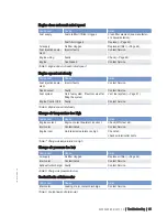
3.1 Firing order

12 V

A1–B2–A5–B4–A3–B1–A6–B5–A2–B3–A4–B6

Direction of rotation

Direction of rotation (as viewed on driving

end)

c.c.w., not reversible

20 | Technical Data | MS15025/00E 2011-12

TIM-ID: 0000032242 - 001

Summary of Contents for MS15025/00E

Page 1: ...Operating Instructions Diesel engine 12 V 1600 R50 MS15025 00E...

Page 2: ...ten permission of MTU Friedrichshafen GmbH This restriction also applies to copyright distribution translation micro filming and storage or processing on electronic systems including data bases and on...

Page 3: ...d installation 39 7 2 Fuel System 41 7 2 1 Fuel system Venting 41 7 3 Fuel Filter 42 7 3 1 Fuel filter Replacement 42 7 3 2 Fuel prefilter Drain condensate 43 7 4 Air Filter 44 7 4 1 Air filter Replac...

Page 4: ...9 Appendix B 9 1 Special Tools 69 9 2 Index 71 4 Table of Contents MS15025 00E 2011 12 DCL ID 0000015960 001...

Page 5: ...other use is considered improper use The engine manufacturer accepts no liability whatsoever for resultant damage or injury in such case The responsibility is borne by the user alone Correct use also...

Page 6: ...accessible to operating maintenance repair and transport personnel at all times Use the manual as a basis for instructing personnel on engine operation and repair In particular person nel must have r...

Page 7: ...cial packaging with aluminum foil suspend the engine on the lifting eyes of the trans port pallet or transport with equipment for heavy loads forklift truck Setting the engine down after transport Pla...

Page 8: ...ring units must be permanently observed with re gard to present operating status violation of limit values and warning or alarm messages The following steps must be taken if a malfunction of the syste...

Page 9: ...ions clean Always seal connections with caps or covers if a line is removed or opened Take care not to damage lines in particular fuel lines during maintenance and repair work Ensure that all retainer...

Page 10: ...haft end until correct sealing is established During hydraulic installation and removal ensure that nobody is standing in the immediate vicinity of the component to be installed removed Working on ele...

Page 11: ...used Laser devices of classes 1 2 or 3A Laser devices of class 3B which have maximum output in the visible wavelength range 400 to 700 nm a maximum output of 5 mW and in which the beam axis and surfac...

Page 12: ...hibited by emission regulations Emission control units systems may only be main tained exchanged or repaired if the components used for this purpose are approved by MTU or equiva lent components Nonco...

Page 13: ...AII and B out of containers results in a risk of explosion Forcing compressed air into thin walled containers e g containers made of tin plastic and glass for drying purposes or to check for leaks res...

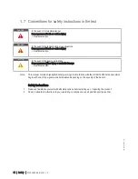
Page 14: ...es Minor injury or material damage Remedial action Note This manual contains highlighted safety warnings in accordance with the US ANSI Z535 standard which begin with one of the signal words listed ab...

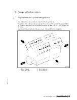
Page 15: ...ted A and those of the right side B as per DIN ISO 1204 The cylinders of each bank are numbered consecutively starting with No 1 at the driving end of the engine Other components are numbered in the s...

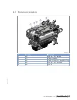
Page 16: ...e free end 13 Cylinder head 14 EGR cooler 15 Engine mounting 16 Engine governor 17 Oil pan 18 Exhaust elbow 19 Intercooler 20 Flywheel housing 21 Flywheel 22 Starter 23 Exhaust turbocharger Engine mod...

Page 17: ...onitoring of 1 B5 1 Lube oil pressure after filter 2 B10 Charge air pressure 3 B9 1 Charge air temperature before EGR mixing 4 B5 3 Lube oil pressure before filter 5 B89 Lambda MS15025 00E 2011 12 Gen...

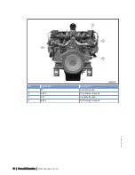
Page 18: ...No Description Monitoring of 1 B1 Camshaft speed 2 B44 2 Turbocharger B speed 3 B13 Crankshaft speed 4 B44 1 Turbocharger A speed 18 General Information MS15025 00E 2011 12 TIM ID 0000035485 001...

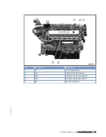
Page 19: ...of 1 B7 Lube oil temperature 2 B43 Charge air coolant pressure 3 B26 Charge air coolant temperature 4 B93 Level and temperature lube oil 5 B6 Coolant temperature MS15025 00E 2011 12 General Informatio...

Page 20: ...Data 3 1 Firing order 12 V A1 B2 A5 B4 A3 B1 A6 B5 A2 B3 A4 B6 Direction of rotation Direction of rotation as viewed on driving end c c w not reversible 20 Technical Data MS15025 00E 2011 12 TIM ID 00...

Page 21: ...3 2 Engine Main dimensions Item Dimensions Height A Approx 1401 mm Length B Approx 1873 mm Width C Approx 1263 mm MS15025 00E 2011 12 Technical Data 21 TIM ID 0000035495 001...

Page 22: ...c pressure mbar 1000 Site altitude above sea level m 100 POWER RELATED DATA power ratings are net brake power to ISO 3046 Number of cylinders 12V Rated engine speed A rpm 1900 Mean piston speed m s 9...

Page 23: ...oil system Option max operating inclinations R liters 63 WEIGHTS MAIN DIMENSIONS Number of cylinders 12V Engine weight dry basic engine configuration acc to scope of delivery specification R kg 2200 A...

Page 24: ...tion Lube oil system Check engine oil level Page 46 Coolant circuit Check engine coolant level Page 49 Check charge air coolant level Page 56 Coolant circuit Preheat engine coolant with coolant prehea...

Page 25: ...001063 Lube oil system Check engine oil level Page 46 Fuel system Vent Page 41 Coolant circuit If engine is out of service for more than one year change engine coolant Page 50 Change charge air coolan...

Page 26: ...sure that nobody is in the danger zone WARNING Engine noise above 85 dB A Risk of damage to hearing Wear ear protectors Starting the engine Item Action Switchgear cabinet control panel etc depending...

Page 27: ...gs of operational data speed temperature pressures Engine oil Check engine oil level Page 46 Engine operation Check engine visually for leaks and general condition Check engine for abnormal running no...

Page 28: ...topping the engine operate it at idle speed until operating temperatures decrease and stable values are indicated Stopping the engine Item Action Temperature indications Wait until engine temperatures...

Page 29: ...vice for an extended period but engine coolant has no antifreeze additive the engine room is not heated the coolant is not kept at a suitable temperature the antifreeze concentration is insufficient f...

Page 30: ...sensors with compressed air Plant Cleaning 1 Carry out plant cleaning only in areas where an appropriate oil separator is provided environmental pro tection 2 Prior to putting the cleaning unit into...

Page 31: ...to QL4 reflect the levels of training offered in MTU courses and the contents of the tool kits required QL1 Operational monitoring and maintenance which can be carried out during a break in operation...

Page 32: ...ply scope these may be disregarded Out of service periods If the engine is to remain out of service for more than 1 month carry out engine preservation procedures in accordance with the Fluids and Lub...

Page 33: ...6 Check engine for abnormal running noises exhaust color and vibrations Page 27 W0507 Drain water and contaminants from fuel prefilter if fitted Page 27 W0508 Check reading on differential pressure ga...

Page 34: ...Engine does not turn when starter is actuated Engine turns but does not fire Component Cause Action Starter Poor rotation by starter Battery low or faulty Charge or replace battery see manu facturer s...

Page 35: ...em Vent fuel system Page 41 Engine Control Unit Faulty Contact Service Table 6 Engine speed not steady Charge air temperature too high Component Cause Action Engine coolant Engine coolant treatment in...

Page 36: ...Oil mist fine separator of crankcase breather clogged Contact Service Exhaust turbocharger Cylinder head Piston rings Cylinder liner Faulty Contact Service Table 11 Blue exhaust gas White exhaust gas...

Page 37: ...F30028346 1 Allen key 5 mm F30002815 1 Barring device F6790714 1 Preparatory steps 1 Remove cylinder head cover Page 39 2 Remove cover on the bottom of flywheel housing A side 3 Install barring devic...

Page 38: ...e reference value exceeds 0 1 mm adjust valve clearance Adjusting valve clearance 1 Loosen locknut 1 and unscrew adjusting screw 2 by a few threads 2 Insert feeler gauge between valve bridge and rocke...

Page 39: ...ing oil 1 Remove screws 2 2 Remove cylinder head cover 1 3 Clean mating faces 4 Check condition of profile gasket and re place if required 5 Position cylinder head cover and screws at positions 1 to 4...

Page 40: ...ening torque using a torque wrench Name Size Type Lubricant Value Standard Screw with twin collar M8 Tightening torque 20 Nm 2 Nm Consecutive tightening sequence starting at po sition 1 1 to 18 40 Tas...

Page 41: ...en flames electrical sparks and ignition sources Do not smoke Venting fuel system 1 Open vent plug 1 Note Catch emerging fuel with a suitable cloth 2 Operate the pump with the handle 2 until bubble fr...

Page 42: ...approx 3 to 4 turns 4 Wait 10 minutes until fuel emerges from fil ter housing 2 5 Remove screw cap 1 with fuel filter ele ment and remove element by pressing it to the side at the lower edge 6 Check...

Page 43: ...f fire and explosion Avoid open flames electrical sparks and ignition sources Do not smoke Draining condensate from fuel prefilter 1 Provide a suitable container to collect the water 2 Open drain scre...

Page 44: ...Preconditions Engine is stopped and starting disabled For air filter replacement carry out operations as specified by the manufacturer filter is plant vehicle manufacturer s supply 44 Task Descriptio...

Page 45: ...ecking signal ring position 1 Replace air filter if the signal ring 2 is completely visible in the red area of the service indicator control window 3 Page 44 2 After installation of new filter press r...

Page 46: ...max marks 4 If necessary top up to max mark Page 47 5 Insert oil dipstick 1 in guide tube up to the stop Checking oil level after the engine is stopped 1 5 minutes after stopping the engine remove oi...

Page 47: ...t with skin Do not inhale oil vapor Draining oil via drain plug on oil pan 1 Provide a suitable container to collect the oil 2 Remove drain plug 2 and drain oil 3 Insert drain plug 2 and use torque wr...

Page 48: ...rew the oil filter covers 1 approx 3 to 4 revolutions 2 Wait 10 minutes until the oil has drained from the filter housings 3 Remove cover 1 with oil filter element 3 and remove oil filter element 3 by...

Page 49: ...n tank counterclockwise to the first stop and allow pressure to escape 2 Continue to turn breather valve counter clockwise and remove 3 Check coolant level coolant must be visible at the lower edge of...

Page 50: ...pecial tools Material Spare parts Designation Use Part No Qty Engine coolant Changing engine coolant 1 Drain engine coolant Page 51 2 Fill with engine coolant Page 53 50 Task Description MS15025 00E 2...

Page 51: ...Preparatory steps 1 Provide an appropriate container to drain the coolant into 2 Switch off preheater if installed Engine coolant Draining 1 Turn breather valve of filler neck on coolant expansion ta...

Page 52: ...rankcase right side 1 2 6 Open drain screws and drain coolant at crankcase left side 1 2 7 Install drain screw with new sealing ring 8 Place breather valve on filler neck and close 52 Task Description...

Page 53: ...coolant in hot engine can cause thermal stress Formation of cracks in components Fill top up coolant only into cold engine Preparatory steps 1 Turn breather valve of filler neck on coolant expansion t...

Page 54: ...Final steps 1 Start the engine and operate it at idle speed for some minutes 2 Check coolant level Page 49 top up if required 54 Task Description MS15025 00E 2011 12 TIM ID 0000000909 003...

Page 55: ...85 dB A Risk of damage to hearing Wear ear protectors Engine coolant pump Relief bore check 1 Check relief bore 1 for coolant discharge Permissible coolant discharge quantity Up to 0 1 ml per hour re...

Page 56: ...on tank counterclockwise to the first stop and allow pressure to escape 2 Continue to turn breather valve counter clockwise and remove 3 Check coolant level coolant must be visible at marking plate 4...

Page 57: ...l tools Material Spare parts Designation Use Part No Qty Charge air coolant Charge air coolant Change 1 Drain charge air coolant Page 58 2 Fill with charge air coolant Page 59 MS15025 00E 2011 12 Task...

Page 58: ...ate container to drain the coolant into 2 Turn breather valve on coolant expansion tank counterclockwise to the first stop and allow pressure to escape 3 Continue to turn breather valve counter clockw...

Page 59: ...thing gloves and goggles safety mask WARNING Engine noise above 85 dB A Risk of damage to hearing Wear ear protectors CAUTION Cold coolant in hot engine can cause thermal stress Formation of cracks in...

Page 60: ...king plate 2 Install plug screws of filling points with new sealing rings 3 Check proper condition of breather valve clean sealing faces if required 4 Fit breather valve and close it Final steps 1 Sta...

Page 61: ...hearing Wear ear protectors Charge air coolant pump Relief bore check 1 Check relief bore 1 for coolant discharge Permissible coolant discharge Up to 0 1 ml per hour respectively 100 ml per 1 000 oper...

Page 62: ...annot swing freely 3 Check that cable ties are firm tighten loose cable ties 4 Replace faulty cable ties 5 Visually inspect the following electrical line components for damage connector housings conta...

Page 63: ...Cleaning 1 Remove coarse dirt from housing surface with isopropyl alcohol 2 Remove dirt from connector and cable surfaces with isopropyl alcohol 3 Check legibility of cable labels Clean or replace ill...

Page 64: ...Control Unit plug connections 1 Check firm seating of all connectors on the Engine Control Unit Make sure that the clips 2 are engaged 2 Check firm seating of all screws 1 on En gine Control Unit cab...

Page 65: ...codes CKT Circuit CLS Coolant level sensor Monitors coolant level CPS Coolant pressure sensor Monitors coolant pressure CTS Coolant temperature sensor Monitors coolant temperature DDEC Detroit Diesel...

Page 66: ...standardization institutes KGS Kraftgegenseite Engine free end in accordance with DIN ISO 1204 KS Kraftseite Engine driving end in accordance with DIN ISO 1204 LED Light Emitting Diode LO Low Alarm Me...

Page 67: ...m alarm TBS Turbocharger Boost Sensor Monitors charge air pressure TCI Turbo Compressor Inlet TCO Turbo Compressor Outlet TD Transmitter Deviation Alarm Deviation in transmitter values TPS Throttle Po...

Page 68: ...r during operation for preventive maintenance corrective work in case of malfunction or changed operating conditions or for spare parts supply Your contact at Headquarters Service support mtu online c...

Page 69: ...auge Part No Y20010128 Qty Used in 1 7 1 1 Valve clearance Check and adjustment Page 37 Ratchet Part No F30027340 Qty Used in 1 7 2 1 Fuel system Venting Page 41 Ratchet adapter Part No F30027340 Qty...

Page 70: ...Qty Used in 1 7 7 1 Engine oil filter Replacement Page 48 Torque wrench 20 100 Nm Part No F30026582 Qty Used in 1 7 1 1 Valve clearance Check and adjustment Page 37 Torque wrench 4 20 Nm Part No F3004...

Page 71: ...gine 46 Check prior to engine start 46 Engine side and cylinder Designations 15 Engine wiring Check 62 F Filter Air Replacement 44 Fire prevention and environmental protection 12 Fluids and lubricants...

Page 72: ...W Wiring engine Check 62 72 Appendix B MS15025 00E 2011 12 DCL ID 0000015960 001...

Reviews: