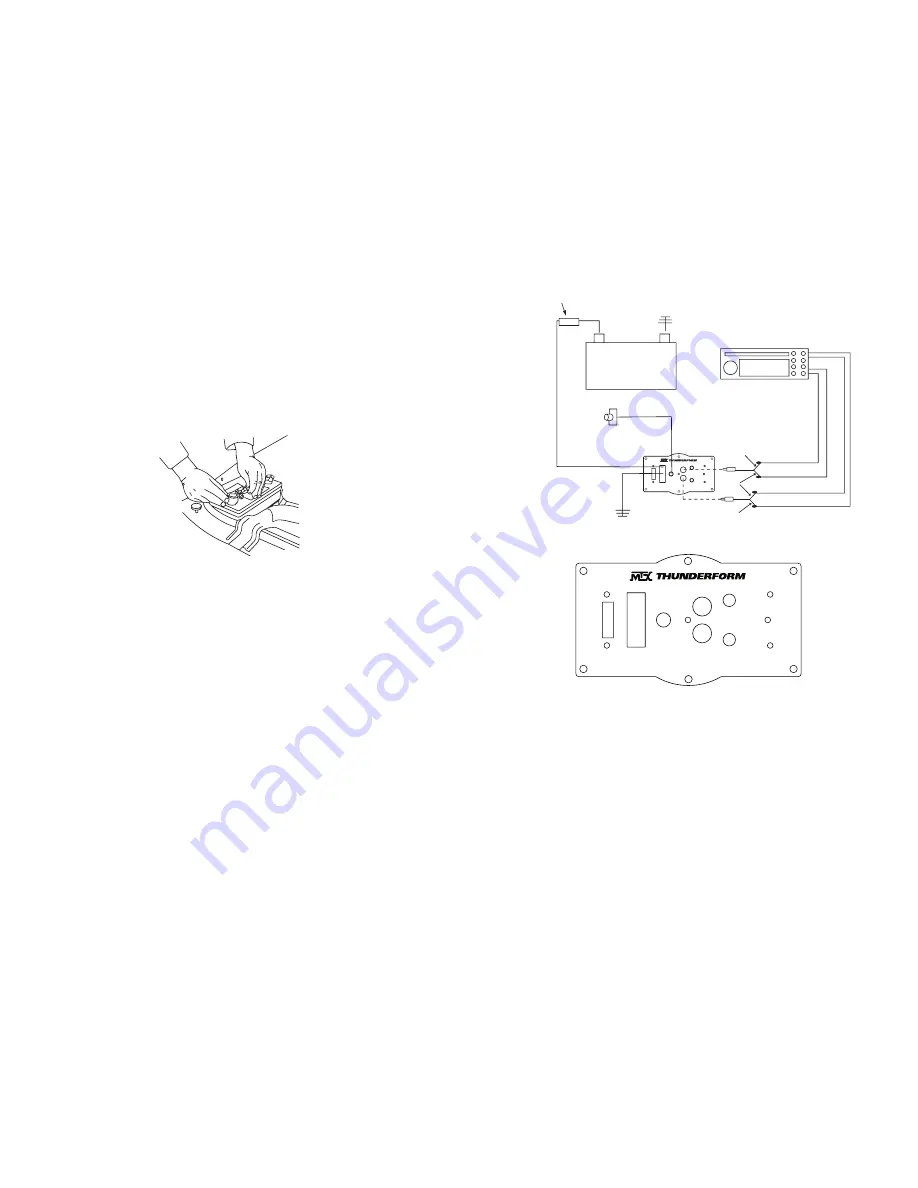
11
. Route 10ga red power wire through a grommet, into the engine
compartment.
12
. Route 10ga red power wire through engine compartment safely away
from any moving or hot parts that could damage the wire.
13
. Cut 10ga red power wire to length, connect the supplied fuse holder
from the wire kit to the end of the wire.
14
. Remove 20amp fuse from MTX fuse holder. Connect furnished ring
terminal to positive side of battery. Remove nut from factory battery ter-
minal. Pass bolt through factory battery terminal, then ring terminal, and
into the other side of factory battery terminal and retighten nut.
15
. Ground amplifier to chassis of vehicle; connect the terminal provided
to the 10ga black wire from furnished wiring harness. A good ground is
as important as the power connection. The ground should be as short as
possible and the contact point should be free of paint and debris.
SPEAKER WIRES
16
. In channel on drivers' side threshold locate the rear speaker wires
located in the smaller of the two wiring harnesses. Colors are right chan-
nel; dark blue (positive) light blue (negative), and left channel; brown
(positive), yellow (negative). Tap into wires with the supplied RCA High
Level input wires and route under carpet beneath the seat, over to pre
amp on enclosure. Depending on the option package, there may be
more than one wire in these colors. The speaker wire will be the smallest
wire.
Although, MTX has made every effort to assure proper wiring colors,
MTX is not responsible for any changes made by the vehicle manufac-
turer which sometime occur. If wiring colors do not match then physical
verification is required.
CONNECTION TO ENCLOSURE
17.
Connect speaker wire RCA's to the inputs of pre-amp.
Note: Patented BTL turn on circuitry- amplifier senses DC offset provided by “high
powered” or BTL type head units. This feature turns the amplifier on automatically
if you are using high level inputs.
_
+
20 Amp Fuse
20
A
PW
R
G
N
D
RE
M
EB
C
INPUT
RI
G
H
T
LE
FT
G
AI
N
X-
O
VE
R
ST
AT
U
S
STRIPED
SOLID
SOLID
Dark Blue (+)
Light Blue (-)
Yellow (-)
Brown (+)
Optional EBC
(Electronic Bass Control)
18
. Plug harness into amplifier pre-amp.
20
A
PW
R
G
N
D
RE
M
EB
C
INPUT
RI
G
H
T
LE
FT
G
AI
N
X-
O
VE
R
ST
AT
U
S
19
. Replace 20amp fuse under hood.
20
. When amp turns on, LED will display red during diagnostic mode and
then to green, signaling amp is on and functioning (amp will only turn on
when radio is on).
21
. Adjust gain and crossover.
Setting Gain
Turn gain knob on Thunderform pre-amp to minimum, counter clock-
wise. Play a favorite tape or compact disc that contains consistent music
and bass. Turn the source unit to maximum listening level. You should
know that some source units will produce distortion or “clip” before the
unit reaches maximum volume. Reduce volume to the loudest listening
level before distortion. Turn the gain knob on the Thunderform pre-amp
clockwise until the speaker starts to distort and reduce gain to loudest
listening level before distortion.
3
4


