background image


PEDAL FLANGER (MUTRON) 

Contents 


Page

    Cover Sheet………………………………………..1 

Contents…………………………………………….2-3 

Introduction………………………………………4 

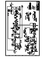
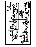
Pedal Flanger Full Schematic………………5 

Main Board Schematic…………………………6 

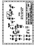
LED/LDR Board Schematic………………….7 

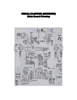
Main Board Overlay…………………………….8 

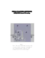
LED/LDR Board Overlay……………………..9 

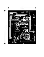
Main Board PCB………………………………….10 

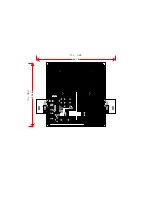
LED/LDR Board PCB…………………………..11 

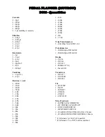
Main Board BOM Quantities…………………12 

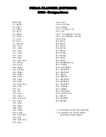
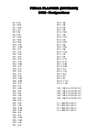
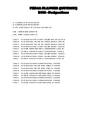
Main Board BOM Designations………........13-15 

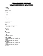
LED/LDR Board BOM Quantities………….16 

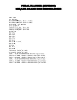
LED/LDR Board BOM Designations………17 

Offboard Wiring…………………………………18 

Offboard Wiring Connectors……………….19 

Summary of Contents for Pedal Flanger 3007

Page 1: ...Feedback Rate Start Stop Pedal Flanger 3007 Input Output Effect Pedal PEDAL FLANGER MUTRON Build Documents 18vdc 12vac...

Page 2: ...ain Board Schematic 6 LED LDR Board Schematic 7 Main Board Overlay 8 LED LDR Board Overlay 9 Main Board PCB 10 LED LDR Board PCB 11 Main Board BOM Quantities 12 Main Board BOM Designations 13 15 LED L...

Page 3: ...es X Wing 22 Drilling Template 23 LED LDR Board Fabrication 24 LED LDR Board LED Indicator Inst 25 Shutter Modification 26 Test Point Fabrication 27 DC Jack Spacer 28 Rate Indicator Installation 29 Ca...

Page 4: ...cluded a transformer mounted in its enclosure This reproduction offers a design that can be powered by either an 18VDC center negative source or a 12VAC wall transformer No switching no component chan...

Page 5: ......

Page 6: ......

Page 7: ......

Page 8: ...PEDAL FLANGER MUTRON Main Board Overlay...

Page 9: ...PEDAL FLANGER MUTRON LED LDR Board Overlay Note D14 D15 are installed on trace side in outer holes on board outriggers See LED LDR Board indicator LED installation for instructions...

Page 10: ...5 32 in 6 50 in 134 5mm 164 7mm...

Page 11: ...111 6mm 4 41 in 3 54 in 89 9mm...

Page 12: ...K 6 39K 6 47K 2 56K 1 91K 3 100K 1 110K 3 120K 1 200K 1 220K 1 270K 5 390K 2 1M 2 1 5M Trim Potentiometers 5 10K Piher N6 L50TOC 103 Potentiometers 3 10KB Alpha RV16AF42 1 50KB Alpha RV16AF42 Diodes 6...

Page 13: ...f C39 01 f C40 4 7 f C41 120pf C41A 10pf C44 4 7 f tant C45 47 f C46 4 7 f tant C47 47 f C48 47 f C49 4 7 f tant C50 1000 f C57 1 5 f tant 1 CX1 1 f CX2 1 f multilayer ceramic CX3 1 f multilayer cera...

Page 14: ...5 10K R40 47K R41 47K R43 1 5K R44 150 R45 270K R46 47K R47 56K R48 100 R49 120K R50 4 7K R51 22K R52 39K R53 39K R54 39K R55 39K R56 750 R57 10K R58 1 5M R59 47K R60 220K R61 56K R62 390K R63 10K R64...

Page 15: ...ER CONNECTOR 2 54MM RIGHT ANGLE CON F WAFER CONNECTOR 2 54MM RIGHT ANGLE CON G WAFER CONNECTOR 2 54MM RIGHT ANGLE CON H WAFER CONNECTOR 2 54MM RIGHT ANGLE CON I WAFER CONNECTOR 2 54MM RIGHT ANGLE CON...

Page 16: ...rs watt 1 330 Trim Potentiometers 2 10K 3362P Diodes 2 5mm LED your choice of color 1 3mm LED yellow diffused Transistors 1 2SC828R ICs 1 RC4558P LDRs 2 Waitrony KE 10720 CONNECTORS 2 WAFER CONNECTOR...

Page 17: ...10720 LDR Q3 2SC828 R42 1 5K R49 1 5K R65 3 3K R66 3 3K R67 24K R68 330R 1 2 watt R69 220K R70 1M R71 56K R72 390K T4 10K 1 4 TRIMPOT 3362P T7 10K 1 4 TRIMPOT 3362P CON J WAFER CONNECTOR RT ANG 3 pin...

Page 18: ...4 5 6 1 2 3 9 8 7 4 5 6 1 2 3 SW2 SW1 PEDAL FLANGER MUTRON OFF BOARD WIRING LEGEND...

Page 19: ...Con E 1 shield Con E 2 SW1 lug8 Con F 1 SW2 lug4 Con F 2 N C Con G 1 Con J pin2 Con G 2 Con J pin3 Con H 1 shield Con H 2 SW1 lug7 Con I 1 SW1 lug1 Con I 2 shield Con J 1 SW2 lug3 Con J 2 Con G pin1 C...

Page 20: ...ly Remove the shutter by inserting a small diameter Phillips screwdriver into the screw access hole on the lower left side of the pedal Modify the shutter see Pedal shutter modification and reinstall...

Page 21: ...or LED installation Remove main board Connect finished female connectors to matching male connectors on both PC boards Labeling each connector simplifies connections Route wires around components and...

Page 22: ...gn the template with the inside lower wall of the enclosure Using tape secure the template in place for accurate drilling of pilot holes If using a X Wing style DPDT switch for SW2 the solder lugs wil...

Page 23: ...RATE LED 5MM STOP POT START POT INSERT DRILLING TEMPLATE IN BOTTOM OF MORLEY ENCLOSURE WITH PRINT FACING YOU WHEN PRINTING TEMPLATE MAKE SURE YOUR PRINTER S SCALING IS SET TO NONE OR 100 CUT ALONG OUT...

Page 24: ...y Optical Volume pedal PC board To fabricate this board first drill multiple holes inside the slot borders Using small files an X acto knife and emery cloth shape the slots to the dimension lines The...

Page 25: ...l indicator D15 LEDs through the outermost holes on the outriggers trace side Flat side cathode facing down On the component side bend the led leads toward the inside of the board Using needle nose pl...

Page 26: ...NE OR 100 Remove shutter from Morley enclosure Place shutter on flat surface Use Xacto knife to extend slot handle of pot shaped figure Slot should be extended 413 10 5mm from back of figure as depict...

Page 27: ...earance between the flanger PC board and the bottom cover standard commercially available test points cannot be used Small low profile test points can be fabricated using medium diameter component lea...

Page 28: ...loth reduce the combined thickness of the two shims for a total thickness of 2mm This spacer thickness allows for centering the jack with the existing hole and leaves an ample amount of the jack pins...

Page 29: ...ED in place Note When building the prototype I fashioned light inhibitors out of black writing pen tube to surround all three indicator LEDs inside of the enclosure When the prototype s LEDs are engag...

Page 30: ...FEEDBACK START STOP controls fully CCW 2 Connect 1 25V to 2 5V 400Hz sinewave to TP3 input 3 Connect oscilloscope to TP2 BBD output 4 Adjust TR1 for best unclipped symmetrical waveform See fig 1 BBD...

Page 31: ...DRs causing inaccurate readings 4 Engage effect switch SW1 Engage pedal switch SW2 5 Adjust TR7 Coarse adjust and TR4 Fine adjust to where voltage readings are approximately 11 60v toe down and 2 29v...

Page 32: ...s the base operating frequency set by the other two components Increasing the capacitance across pins 6 7 will decrease the frequency During the course of calibrating the flanger prototype I started w...

Page 33: ...6 1 2 3 9 8 7 4 5 6 1 2 3 SW2 SW1 TR6 UPPER FREQ TR2 BALANCE TR3 BBD OUTPUT TR1 BIAS TR5 LOWER FREQ TP1 TP2 TP3 TP4 TP5 TP6 TR7 COARSE ADJUST TR4 FINE ADJUST PEDAL FLANGER MUTRON TEST POINT TRIMMER LE...

Page 34: ...Feedback Rate Start Stop Pedal Flanger 3007 Input Output Effect Pedal 12vac 18vdc...

Reviews: