PEDAL FLANGER (MUTRON)
Rate indicator installation
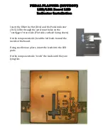
Install
rate
indicator
LED
after
the
populated
main
board
has
been
installed
and
checked
for
proper
alignment.
Remove
main
board
and
insert
the
rate
LED,
flat
side
(cathode)
down
onto
the
component
side.
Bend
the
LED
leads
slightly
to
keep
the
LED
in
place.
Install
the
main
board
into
the
enclosure.
Tighten
the
jack
and
control
nuts.
Adjust
the
rate
LEDs
height
to
match
the
Effect
In/Out
and
the
Pedal
indicator
LEDs
height
from
the
top
side
of
the
enclosure.
Flip
the
enclosure
upside
down
and
solder
the
Rate
LED
in
place.
Note:
When
building
the
prototype,
I
fashioned
light
inhibitors
out
of
black
writing
pen
tube
to
surround
all
three
indicator
LEDs
inside
of
the
enclosure.
When
the
prototype’s
LEDs
are
engaged,
no
light
from
the
indicator
LEDs
is
visible
inside
the
enclosure.
Light
from
the
LEDs
could
reflect
off
of
components
and/or
be
cast
as
ambient
light
disturbing
the
workings
of
the
pedal
C.V.
circuit.
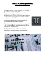
To
fabricate
the
light
inhibitors,
cut
three
pieces
of
pen
tube,
1
@
.798”
(20.28mm)
for
the
rate
LED,
and
two
@
.202”
(5.13mm)
for
the
Effect
In/Out
and
Pedal
LEDs.
Ream
out
one
end
of
the
pen
tube
with
a
step
bit
or
a
proper
sized
drill
bit
so
that
the
back
of
the
LED
fits
inside
of
the
tube
forming
a
stop.
The
pen
I
used
is
a
Papermate
model
#
PAP3331131
or
PAP3381131.
Summary of Contents for Pedal Flanger 3007
Page 5: ......
Page 6: ......
Page 7: ......
Page 8: ...PEDAL FLANGER MUTRON Main Board Overlay...
Page 10: ...5 32 in 6 50 in 134 5mm 164 7mm...
Page 11: ...111 6mm 4 41 in 3 54 in 89 9mm...
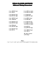
Page 18: ...4 5 6 1 2 3 9 8 7 4 5 6 1 2 3 SW2 SW1 PEDAL FLANGER MUTRON OFF BOARD WIRING LEGEND...
Page 34: ...Feedback Rate Start Stop Pedal Flanger 3007 Input Output Effect Pedal 12vac 18vdc...

