PEDAL FLANGER (MUTRON)
¾
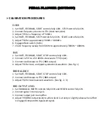
CALIBRATION
PROCEDURES
PEDAL
SWEEP
RANGE
1.
For
best
results,
perform
this
procedure
away
from
direct
light
source.
2.
With
enclosure
positioned
on
its
side,
connect
voltmeter
to
TP6
(GND)
and
TP5
(Pedal
CV)
3.
Cover
entire
enclosure
with
dark
cloth
material
to
keep
ambient
light
from
reaching
LDRs
causing
inaccurate
readings.
4.
Engage
effect
switch
(SW1)
Engage
pedal
switch
(SW2)
5.
Adjust
TR7
(Coarse
adjust)
and
TR4
(Fine
adjust)
to
where
voltage
readings
are
approximately
11.60v
(toe
down)
and
2.29v
(heel
down)
6.
Due
to
variances
in
LEDs
and
LDRs,
It
may
be
necessary
to
adjust
D18,
LDR1,
LDR2
‐
up,
down,
right
or
left
to
achieve
the
target
voltages.
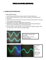
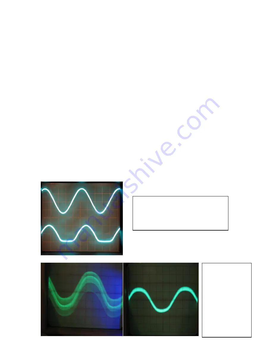
Fig.
1
Fig.
2
Fig.
3
Top
image
– Sine
wave
after
adjustment.
Bottom
image
–
Sine
wave
displaying
clipping.
Left
image
–
BBD
outputs
unbalanced.
Right
image
–
BBD
outputs
Balanced.
Summary of Contents for Pedal Flanger 3007
Page 5: ......
Page 6: ......
Page 7: ......
Page 8: ...PEDAL FLANGER MUTRON Main Board Overlay...
Page 10: ...5 32 in 6 50 in 134 5mm 164 7mm...
Page 11: ...111 6mm 4 41 in 3 54 in 89 9mm...
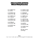
Page 18: ...4 5 6 1 2 3 9 8 7 4 5 6 1 2 3 SW2 SW1 PEDAL FLANGER MUTRON OFF BOARD WIRING LEGEND...
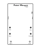
Page 34: ...Feedback Rate Start Stop Pedal Flanger 3007 Input Output Effect Pedal 12vac 18vdc...

