background image

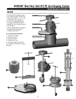
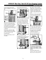
G.

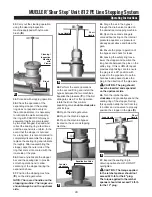
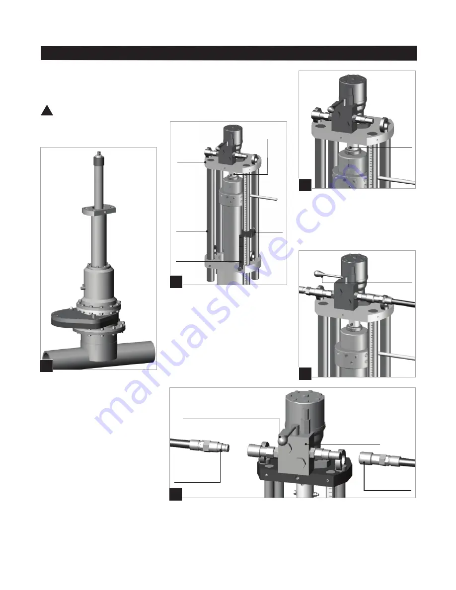
Lever turned 

90° clockwise:

shaft turns 

clockwise

8. Remove the handles.
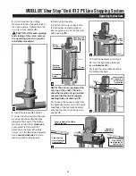
9. Position the motor support onto 

the boring bar operating square. 

Ensure guide columns are lined up 

with housings (

D.

). 

NOTE: There is an opening at the 

very top of the shaft. This is to 

allow the insertion of a pin, which 

ensures that the motor support 

bushing does not slide out (

e.

).

10. Connect the hoses coming from 

the hydraulic control unit to the quick 

couplings of the hydraulic operator 

ensuring the lever is in the neutral 

position (

F.

).

MUELLER

® 


Shur Stop

TM

 Unit 812 PE Line Stopping System

Operating Instructions

8

11. Start the hydraulic control unit.
12. Turn the hydraulic distributor 

lever clockwise (

G.

). 

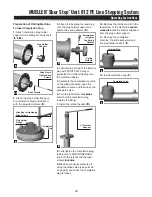
13. Insert the removable handle in 

the drilling machine.

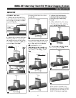
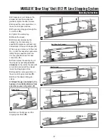
5. Lift and position the drilling 

machine onto the slide gate valve in 

the open position. Tighten the bolts 

in a criss-cross fashion (

C.

).

       CAUTIoN: After each opening 

and closing of the valve, remove 

the operating wrench to prevent 

accidental movement.

6. Insert the removable handles 
7. Lower the shell cutter to the pipe 

by using the removable handles 

placed on the head of the drilling 

machine, turning them clockwise 

until contact is made with the 

pilot drill on the pipe. When this 

occurs, turn the feed tube a quarter 

turn counter-clockwise to avoid 

jamming when drilling begins.

!

C.

F.

Hydraulic

Distributor

Lever in Neutral Position: 

Shaft Stopped

Pipe coming 

from Hydraulic 

Control Unit

Pipe coming 

from Hydraulic 

Control Unit

e.

Anti-

Slide

Pin

D.

Graduated

Scale

Collar

Motor 

Support

Bushing with 

Control Screw

Guiding

Columns

Summary of Contents for ShurStop 812 PE

Page 1: ...ty damage 3 Safety goggles and other appropriate protective gear should be used Failure to do so could result in serious injury 4 Pressure test check for and repair leaks in all fittings and component...

Page 2: ...re of 125psig Actual MAOP will be dependent on the operating pressure of the PE pipe This manual describes all operations including drilling stopping and completion plug insertion Basic Equipment Requ...

Page 3: ...ectrofusion housing with metal bushing Completion plug with two O rings Completion cap with one O ring NOTE These fittings are compatible with any universal processor available on the market equipped...

Page 4: ...he valve is fitted with an internal pressure equalizer which allows easy opening when pressure varies between the upper and lower parts of the valve To open and close the valve turn the operating squa...

Page 5: ...ll be working It also allows inspection of the fittings internal threads and cleaning if necessary before installing completion plug Cleaning Inspection machine H L W Bleed Valve Brush Rod Viewer insi...

Page 6: ...until the pipe holder is in contact with the pipe D D1 CAUTION The best compression is the one where it is impossible to insert a sheet of paper between the fitting and the pipe 5 Perform the electro...

Page 7: ...ur Stop TM Unit 812 PE Line Stopping System Operating Instructions 7 G PE Pipe 8 12 20 Vent Fitting H Combined Wrench A1 A Pilot Bit Allen Key for tightening B Shell Cutter Adjustment Flange Eyebolt S...

Page 8: ...13 Insert the removable handle in the drilling machine 5 Lift and position the drilling machine onto the slide gate valve in the open position Tighten the bolts in a criss cross fashion C CAUTION Afte...

Page 9: ...d out J 22 Loosen the knob on the graduated scale turn the graduated scale 90 counter clockwise and then tighten the knob K J Collar 23 Open the oil flow and begin drilling again until the pipe coupon...

Page 10: ...gate valve without acting on the internal pressure equalizer as pressure is already equal above and below the gate 44 Ensure the proper operation of the bypass and check for leaks 45 Leaving the safet...

Page 11: ...out of the vent No 2 close the respective gate valve letting the gas equalize pressure It is now possible to test the new connections T 54 Decompress the sealing ring of the stopper by operating coun...

Page 12: ...d check the completion plug for leaks MUELLER Shur Stop TM Unit 812 PE Line Stopping System Operating Instructions 12 Preparation of Drilling Machine To Insert Completion Plug 1 Attach completion plug...

Page 13: ...nspection cleaning machine Inadequate sealing of the Insufficient tightening of the screws sealing disk of the flange that compresses the Tighten the screws slightly sealing disk Inadequate sealing of...

Page 14: ...MUELLER Shur Stop TM Unit 812 PE Line Stopping System Notes 14...

Page 15: ...MUELLER Shur Stop TM Unit 812 PE Line Stopping System Notes 15...

Page 16: ...s document herein are the property of Mueller Co LLC its affiliates or other third parties Products marked with a section symbol are subject to patents or patent applications For details visit www mwp...

Reviews: