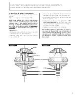
HYDRANT VALVE RUBBER REPLACEMENT
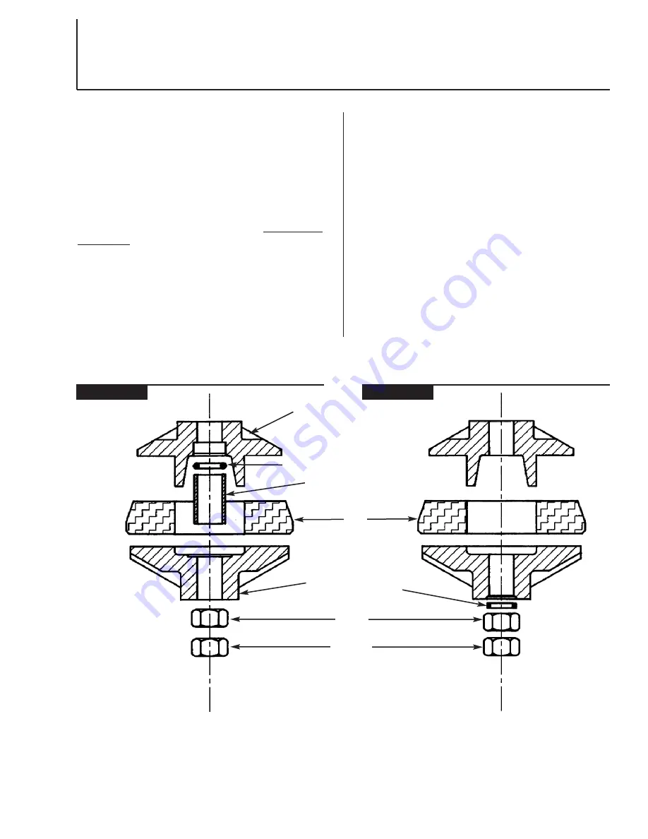
Figure 1 (illustrated below) is current production
method.
Figure 2 was supplied prior to August, 1984.
NOTE: Valve ball top (P/N 450) as currently sup -
plied on hydrant assemblies (Figure 1) can also be
used for Figure 2. Valve ball bot.tom (P/N 485) as
currently supplied is not inter changeable, how -
ever, valve ball bottoms supplied on replace ment
part orders will be suitable for either Figure 1 or 2.
PROCEDURE
• Place valve rubber (P/N 515) on valve top (P/N
450) and position on hydrant rod end.
• Lubricate O-ring (P/N 41301) and slide carefully
over rod threads.
5
CENTURY, B-50-B18 AND B-50-B24 FIRE HYDRANTS
Internal Parts Removal and Hydrant Valve Rubber Replacement
• Slide plastic sleeve (P/N 294403) over rod end and
use sleeve to position O-ring in recess in valve top.
• Position valve bottom on rod and run rod nut out
(P/N 46140) into position.
• Using wrench, "snug" assembly together –
DO
NOT OVER TIGHTEN
rod nut. Tightening of the
rod nut should not cause noticeable bulging or
distortion of the valve rubber.
• Tighten second rod nut into first for locking.
NOTE: When replacing valve rubber on Figure 2,
care must be exercised to prevent rotation of
valve assembly when tightening rod nut. Proper
compression of gasket and effective sealing is
not obtained if valve is allowed to rotate with
the rod nut.
FIGURE 1
FIGURE 2
450
485
515
1988
46140
362818
41301
294403
Summary of Contents for B-50-B18
Page 7: ...7 CENTURY B 50 B18 AND B 50 B24 FIRE HYDRANTS Notes...
Page 8: ......

