8
Installation of Tandem Stems
Some gates have wide openings
with relatively short gate heights.
When the installation drawings
show tandem lifts, install each lift
in accordance with the preceding
steps 1 – 5. After each lift has
been installed and each stem is
connected to the gate slide at
the bottom and the lift at the top,
proceed as follows:
1.
Turn the input shaft of each lift
in the direction to open the gate
until each stem makes firm contact
with the top of its connection on
the gate slide.
2.
Place a level on the top of the
gate slide and move one stem or
the other of the gate up or down
until the slide is completely level.
3.
A tandem interconnecting shaft
is furnished to connect the two lifts
and cause them to act in unison
for raising or lowering the gate.
Loosen the fasteners on one of
the jaws of the flexible coupling
and slide it toward the center of
the shaft until the shaft can be
connected between the two lifts.
Complete the connection and
retighten all fasteners.
4.
Move the gate slide up and
down by turning the input shaft
of one lift. Ensure the gate is
installed with its top level and that
the gate is moving freely.
5.
Complete the installation of
any stem guides, lubricate the
stem, adjust the stop nuts, etc, as
described in the preceding steps
1 – 9 in the section entitled Lift
Installation and Adjustment of
Stem Guides for gates not self-
contained.
Gate Adjustment
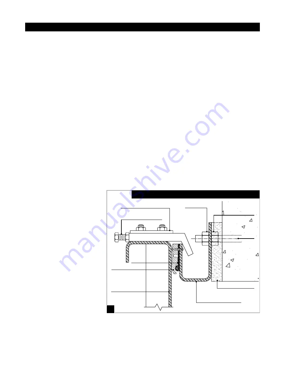
This gate is equipped with low-
friction polyethylene (UHMWPE)
seats and guides. The seats
rest on a neoprene (rubber) pad
for cushioned gasketing to the
frame. Sealing at the side is
accomplished by pinching the
seal lips against the slide plate
using the compression of the
rubber gasket pad. Top horizontal
member seal (and also bottom, if
seals are 4-sided) are loaded by
the compression pad and assisted
with ensured hook-type wedges
on medium and larger width gates
(Fig. A & J).
This gate has been factory
adjusted. However, if the shake-
proof nuts have been loosened,
readjustment may be required.
Visual Tightness of the Seat
against the Side
No light should be visible through
the seat or measurable gaps
between the slide plate and the
seat. A .004" gauge may be
used to check the seat gap as a
starting point; however, the best
test and proof of performance
is an unseating hydrostatic
test. This gate is required to
comply with AWWA C561 leakage
specifications.
HG561 FABRICATED SLIDE GATE
Installation
9
J.
Gate Frame
Grout
Anchor
Slide Plate
SIDE VIEW OF BOTTOM SECTION SHOWING SEAL ARRANGEMENT
Wedge Adjustment Bolt
Adjusting Nut
Top Nut
UHMW
Polymer
Seal
Neoprene Load Pad
Cast Stainless Steel Wedge

