2.6
Electrical Requirements and Field Wiring Instructions (460/60/3 Models)
1.
Connect a fused disconnect providing a 460/60/3 power supply to terminals L1, L2, and L3 in the
electrical enclosure.
2.
Ensure that the primary connections on the transformer are connected for the proper supply
voltage, connections H1 and H6 for 460 VAC supplies.
3.
Connect the 24 VAC control circuit wiring for each condensing unit to the corresponding terminals
S1-S4 located in the electrical enclosure.
4.
Check and adjust magnetic starter overload amperage setting according to Table 2.
5.
Ensure that 0.5-amp fuses are in place for the primary supply of the transformer.
6.
Ensure that the circulation pump is wired for 460 VAC. (Check the circulation pump for proper
rotation after the reservoir has been filled with liquid. Do not operate the pump dry.)
7.
Inspect and tighten all factory and field wiring connections before applying power.
Table 1 - 240 VAC, 3 Phase
Table 2 - 480 VAC, 3 Phase
2.7
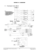
Condensing Unit Low-Voltage Circuit Wiring
To ensure proper operation of the temperature control staging connect the condensing unit control
circuits as follows:
a.
Connect condensing unit number one to the control circuit S1, terminal numbers 2 and 6.
b.
Connect condensing unit number two to the control circuit S2, terminal numbers 2 and 7.
c.
Connect condensing unit number three to the control circuit S3, terminal numbers 2 and 8.
d.
Connect condensing unit number four to the control circuit S4, terminal numbers 2 and 9.
Chiller Control Model 200 Installation and Operation Manual
3
Effective June 22, 2000
Part No. 9843143
Revised April 8, 2002
Motor
Amp Draw
Amp Draw
Amp
Fuse
Fuse
Overload
HP
Pump Motor
Transformer
Range
Part No.
Amperage
Part No.
0.5
2.0
.31
1.6-2.5
507785
1 AMP
9842339
.75
2.8
.31
2.5-4.0
507785
1 AMP
9842342
1.0
3.6
.31
2.5-4.0
507785
1 AMP
9842342
1.5
5.2
.31
4.0-6.3
507785
1 AMP
9842362
2.0
6.8
.31
6.3-9.0
507785
1 AMP
9842343
3.0
9.6
.31
9.0-12.5
507785
1 AMP
9842382
Motor
Amp Draw
Amp Draw
Amp
Fuse
Fuse
Overload
HP
Pump Motor
Transformer
Range
Part No.
Amperage
Part No.
0.5
1.0
.16
1.0-1.6
9820107
.5 AMP
9842757
.75
1.4
.16
1.0-1.6
9820107
.5 AMP
9842757
1.0
1.8
.16
1.6-2.5
9820107
.5 AMP
9842339
1.5
2.6
.16
2.5-4.0
9820107
.5 AMP
9842342
2.0
3.4
.16
2.5-4.0
9820107
.5 AMP
9842342
3.0
4.8
.16
4.0-6.3
9820107
.5 AMP
9842362
5.0
7.6
.16
6.3-9.0
9820107
.5 AMP
9842343
Summary of Contents for Hydro-Guard 200 Series
Page 14: ......


