background image

TABLE OF CONTENTS 

PAGE

OPERATING INSTRUCTIONS MANUAL

        WARNING: 

1. Each person involved in the assembly, installation and/or maintenance of the 

Hydro-Guard Automatic Flushing Device must read this manual carefully and follow 

all instructions prior to performing any installation or maintenance procedures 

involving the Unit. 

2. Verify the drainage path prior to installation to ensure that pedestrian and 

vehicular hazards will not be created by the installation and use of the Hydro-

Guard Automatic Flushing Device (In areas in which freezing may occur, special 

attention should be given to this procedure). 

3. Never assemble, disassemble, or perform Hydro-Guard maintenance unless the 

influent supply valve has been closed, verified and secured, and internal piping 

pressure has been relieved. 

4. Always use all necessary safety equipment and follow all recommended 

procedures when installing, operating and maintaining the Hydro-Guard Automatic 

Flushing Device. 

5. Replace worn or defective parts with OEM parts and check your battery twice a 

year. 

6. Operate the Hydro-Guard Automatic Flushing Device only when fully installed and 

correctly assembled. 

7. It is recommended that a pressure reducing valve be installed in front of the 

Hydro-Guard where pressure could exceed 120psi. 

        CAUTION: 

The recommended optimal operating pressure for a Hydro-Guard® Automatic Flushing 

System is between 20psi and 120psi. In the event pressure may exceed 120psi it 

is recommended that a Pressure Regulating Valve be installed ahead of the Hydro-

Guard flushing system. 

Customer Service Center  

Decatur, Illinois  

800.798,3131  

www.muellercompany.com/hydro-guard  

moreinfo@muellercompany.com

HG-2  

Low-Profile  

Direct  Discharge  

Unit

Installation Instructions  

2

Programming Unit  

3-8 

Options and Upgrades  

9

Disassembly/Reassembly of Unit  

10

Troubleshooting 11

Parts 12-13

F 12771 1/21

!

!

Summary of Contents for Hydro-Guard HG-2

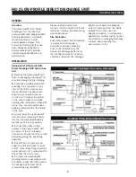
Page 1: ...ipment and follow all recommended procedures when installing operating and maintaining the Hydro Guard Automatic Flushing Device 5 Replace worn or defective parts with OEM parts and check your battery...

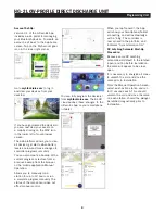
Page 2: ...g it is connected on one side to the utility s service line trench Remove any debris that might create uneven pressure on the Unit Compact the bottom of the hole in order to minimize settling after in...

Page 3: ...3 Launch the application on your Smartphone or Tablet 4 Associate the controller with your phone by tapping the Add a Controller button 5 The app will now ask what type of Bluetooth device you would l...

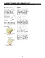
Page 4: ...ontroller The controller home screen has the option to manually run the system fully program the controller with up to 8 start times and 8 independent programs and to turn the device off permanently o...

Page 5: ...tore from a previous backup from the browser or the mobile application Manual Operation Allows you to manually run a station for up to 12 hours or run a complete program manually The status of the rai...

Page 6: ...to other parts of any installation of which this product is part The warranty shall not apply to any equipment which is found to have been improperly installed set up or used in any way not in accord...

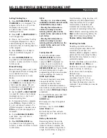
Page 7: ...Insert battery batteries into battery tray and connect the battery connector to controller 3 Make sure no water is inside battery compartment 4 Screw the NODE rear body back onto front half NOTE Make...

Page 8: ...e program 4 Press PRG key to set days to flush for a different program if desired 5 Press RETURN ENTER key to proceed to next programming function or allow controller to return to Idle mode Manual Flu...

Page 9: ...The following is a brief overview and introduction to Hydro Guard Options Sample Station A standard feature on the HG 2 Low Profile Direct Discharge Unit is the sample port which allows Hydro Guard s...

Page 10: ...lilting slightly on its end Once the retaining pin located in the opposite end of the housing is clear of the cover lilt upward to remove the cover 3 Use the sample port connection to bleed off resid...

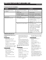
Page 11: ...e flow The water pressure Is too high and the solenoid will not close Try this Correction Run a manual flush for 1 minute Change batteries Check connections for corrosion breaks or lack of connection...

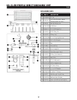
Page 12: ...1 Bushing Machined 9 HG 14016 1 x 4 PVC Nipple 10 HG 01100 Cap 11 HG S258 Controller Clip 12 HG 13140 2 90 Elbow TxT 13 HG 13210 Controller Support Clamp 14 HG S138 2 Male Union Assembly 15 HG 01157...

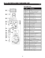
Page 13: ...Coupling SxT 10 HG 02108 2 x 7 SxT PVC 11 HG 02112B Support Bracket 12 HG S139 RP2 Sub Assembly 13 HG 02112 Brace 14 HG 021128 Support Bracket 15 HG S255 Latching Solenoid Assembly 7 16 HG V117H Valve...

Page 14: ...14 NOTES...

Page 15: ...15 NOTES...

Page 16: ...cts Inc All Rights Reserved The trademarks logos and service marks displayed in this document are the property of Mueller Water Products Inc its affiliates or other third parties Products marked with...

Reviews: