background image

2

HG-3 FLUSHING SYSTEM

Installation Instructions

GENERAL

INSTALLATION

performance. Please read and 
retain this manual.

Site Evaluation

Each Hydro-Guard® Flushing System 
installation is unique and will 
require a minimum of advance 
planning. Prior to the installation of 
the device, the drainage patterns 
for the intended installation location 
should be reviewed. The drainage 

to prevent erosion. Inspect the 
area immediately around the Unit 
in order to ensure that the existing 
ground cover is not subject to 
severe erosion. You may opt to pour 
a concrete pad or create a custom 
installation to best suit your needs.

7.

 Disinfect the Hydro-Guard® 

Flushing Device in accordance 
with the utility's policy. DO NOT 

Overview

The Hydro-Guard® HG-3 Automatic 
Flushing System, the industry's 
premium patented, programmable 
flushing apparatus, is suitable 
for year-round use in moderate 
to severe cold climates. This 
Automatic Flushing System has 
been designed, engineered, 
and manufactured to provide 
outstanding dependability and 

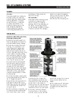
Hydro-Guard HG-1 Atmospherically 
Discharged Flushing Unit
1.

 Remove the Hydro-Guard® Unit 

from Its packaging and inspect for 
possible damage during shipping.

2.

 Excavate a suitably-sized ditch 

ensuring it is connected on one 
side to the utility's service line 
trench. Remove any debris that 
might create uneven pressure on 
the Unit. Compact the bottom of the 
hole in order to minimize settling 
after installation. Place #57 stone, 
then non-compacted clean bedding 
material within the bottom of the 
hole. Turn off service line feed. 

3.

 Slowly lower the Hydro-Guard® 

Unit into place, pressing it firmly 
into the noncompacted bedding 
material until it Is fully seated. 
Ensure that the Unit is level before 
beginning the backfilling operation 
(The bottom of the ground plate 
should be approximately 1" above 
the final grade).

4.

 Connect the utility's water system 

to the Hydro-Guard® Unit by means of 
the 2" threaded connection.

5.

 Backfill the hole around the Unit 

with clean fill and/or #57 stone. 
Backfilling should be accomplished 
in 6" compacted lifts. Check that 
the Unit is level.

6.

 After installation is complete, sod 

the area around the Hydro-Guard® 
Unit or take other steps in order 

pattern must permit discharged 
water to flow away from the Hydro-
Guard® Flushing Unit or to be 
absorbed by the surrounding soil. 

exceed the dosage and contact 
times recommended by the 
AWWA.

8.

 The Hydro-Guard® Automatic 

Flushing Device may now be 
pro grammed and placed Into 
service.

Summary of Contents for Hydro-Guard HG-3

Page 1: ...piping pressure has been relieved 4 Always use all necessary safety equipment and follow all recommended procedures when installing operating and maintaining the Hydro Guard Automatic Flushing Device 5 Perform annual safety inspections and replace worn or defective parts 6 Operate the Hydro Guard Automatic Flushing Device only when fully installed and correctly assembled CAUTION The recommended op...

Page 2: ...ect for possible damage during shipping 2 Excavate a suitably sized ditch ensuring it is connected on one side to the utility s service line trench Remove any debris that might create uneven pressure on the Unit Compact the bottom of the hole in order to minimize settling after installation Place 57 stone then non compacted clean bedding material within the bottom of the hole Turn off service line...

Page 3: ...noids will come from the manufacturer with the plunger already magnetically latched open some zones will default to OPEN Follow the start up procedure for systems with DC Latching Solenoids Page 09 CAUTION For every change to the program in the Mobile App you must exit back to the home screen and tap the blue TRANSMIT button bottom right corner The Application aggregates changes and transmits them...

Page 4: ...red HG 3 Battery Replacement 1 Shut off water supply to unit 2 Use HG A2023 Security Tool to unlock and remove protective Exterior Housing Cover 3 Unscrew protective cap from gray Programming Interface which is located at top of unit 4 Extract battery harness and remove old battery dispose of battery appropriately 5 Connect fresh industrial grade 9 volt lithium or alkaline battery and reinsert it ...

Page 5: ...eak or dead Connection loss from controller to solenoid Solenoid not working properly Obstruction In flow of water Trv this Correction Check If curb stop Is open Change batteries Check connections for corrosion breaks or lack of connection Run a manual flush and confirm the solenoid plunger is kicking out and pulling back in by listening for a click Check to make sure the flow control knob is open...

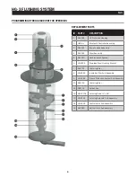
Page 6: ...embly 4 546329 Riser Assembly 5 546519 Dechlorination System 6 HG S316 Stainless Steel Housing Bracket 7 545729 Centering Star 8 HG S126 Insulation Star Sub Assembly 9 HG S128 Freeze Protection System Sub Assembly 10 545729 Centering Star 11 545738 Splash Pad 12 HG 13105 Latching Rods x 26 13 HG S124 Latching Solenoid Sub Assembly 14 HG S325 Control Valve Sub Assembly 15 546330 Bottom Plate Sub As...

Page 7: ...ts and services MWP does not provide products or services to third parties MWP and each of its subsidiaries are liable only for their own acts and omissions and not those of each other MWP brands include Mueller Echologics Hydro Gate Hydro Guard HYMAX Jones Krausz Mi Net Milliken Pratt Singer and U S Pipe Valve Hydrant Please see muellerwp com brands and krauszusa com to learn more 2020 Mueller Wa...

Reviews: