6 | 16
M0701.docx |
Rev 1.5 | Modified on 26/03/2021
| © Remote Control Technologies Pty Ltd
CONTROL UNIT STATUS INDICATOR OPERATION
STATE
INDICATOR SEQUENCE
Battery Power-up
■
All indicators will turn on.
■
All indicators will turn off.
■
After power-up, the control unit will revert to normal operation.
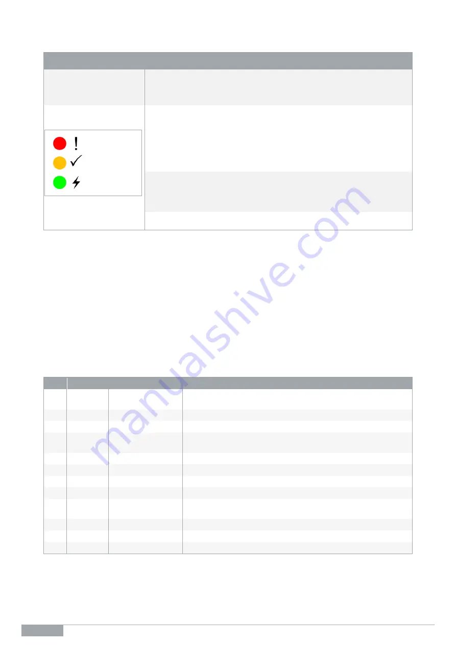
Status Indicator in
Operation
RED
– Fault.
■
If outputs have problems, this will turn on.
■
Outputs 1 & 2
– high current outputs: checked for over current.
■
Output 3
– not checked as it is a low side driver.
■
Output 4
– checked for correct output voltage.
■
Temperature
– checked for board temperature exceeding 80 °C.
YELLOW
– Pulses during normal operation, indicates system OK.
■
Flashes on and off at one-second intervals (on for one second, off for
one second).
GREEN
– On for normal operation.
INSTALLATION INSTRUCTIONS
1.
Mount the control unit in suitable location.
2.
Refer to the wiring table below and the wiring diagram in this manual to connect the control unit.
It is recommended that the wiring is installed alongside the OEM wiring ensuring that it is secured at regular
intervals; this will provide protection from heat and abrasion, and any other excess damage that may occur
with extended vehicle operation. When securing the wiring to the OEM wiring, ensure that the loom is away
from moving vehicle parts which could lead to loom damage.
3.
Mount the LED on the instrument panel in the cabin clear view of the operator.
WIRING CONNECTIONS
NO.
COLOUR
FUNCTIONS
DESCRIPTION
1
Red
Ignition Input
Keyed override switch (11386 kit only). Connect to the ignition
supply at the key switch (ensure it is circuit breaker protected).
2
Black
Ground
Earth
3
Green
Output 1
Flashing LED +ve (13 A)
4
-
Output 3
Optional output (solid). Please that wires must be added to the
supplied loom if you wish to use this output.
5
-
Input 1
Not used
6
Blue
Input 3
Left door switch input
7
Blue
Input 4
Right door switch input (11387 kit join BU wire to BK wire - earth)
8
Grey
Input 2
Park brake switch input
9
-
Output 4
Optional output (flashing). Please that wires must be added to the
supplied loom if you wish to use this output.
10
White
Output 2
OEM horn +ve (13 A)
11
-
Battery Supply
–ve Not used
12
-
Battery ve Not used
Note
: Manufacturer recommends that the Pin 10 Output - (white) be connected to the OEM horn circuit via a
relay if the current draw is greater than 13 amps.
Alarm Indication
System Status
Power Indication
Summary of Contents for 11377
Page 1: ...PRODUCT MANUAL PARK BRAKE WARNING SYSTEM 12 24 VOLTS Part No 11377 11386 11387 ...
Page 14: ...14 16 M0701 docx Rev 1 5 Modified on 26 03 2021 Remote Control Technologies Pty Ltd NOTES ...
Page 15: ...M0701 docx Rev 1 5 Modified on 26 03 2021 Remote Control Technologies Pty Ltd 15 16 NOTES ...


