Summary of Contents for 5884

Page 1: ...PRODUCT MANUAL FIRE SYSTEM STATUS PANEL Part No 5884 ...

Page 2: ...or infringements upon the rights of third parties that may result from its use All examples and diagrams shown in this manual are intended only as an aid to understanding the text not to guarantee operation RCT will accept no responsibility for actual use of the product based on these illustrative examples Please contact your nearest RCT branch for more information concerning applications in life ...

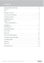
Page 3: ... 6 Operation and Use 7 Installation Guide 8 Wiring Connections 8 Diagrams 9 External Wiring Diagram 300o 9 ETR External Wiring Diagram 478i 10 Calibration 11 Calibration CAL Mode 11 No Extension Mode 11 Service Information 11 Service Schedule 11 Service Procedure 11 Parts List 12 Technical Specifications 12 Compliance and Standards 12 Troubleshooting 13 Glossary 14 Warranty 14 Revision History 15 ...

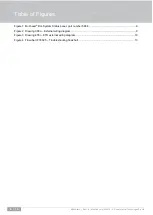
Page 4: ...rol Technologies Pty Ltd Table of Figures Figure 1 Muirhead Fire System Status panel part number 5884 6 Figure 2 Drawing 300o External wiring diagram 9 Figure 3 Drawing 478i ETR external wiring diagram 10 Figure 4 Flowchart FC0025 Troubleshooting flowchart 13 ...

Page 5: ...o protect the machine and other equipment in the area Do not operate any machine with a known fault and report all findings to the supervisor in writing Test and operate machine as per machine OEM and site procedures Read and understand machine and site specific operational and testing instructions Product Before applying power to the equipment the user repairer installer must read all product ins...

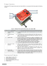
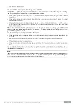
Page 6: ...d indicated by the alarm switching from continuous to pulsing The ETR output deactivates whilst the auxiliary output activates The red alert indicator flashes when the override is activated 4 Panel Test 1 Shot Override When the cylinder pressure is correct the panel test button acts as a test button When the button is pressed the system will simulate that the fire system has been set off When the ...

Page 7: ...he cylinder pressure is discharged input 2 open a timing cycle is initiated At the end of the time period default setting of six seconds the alarm pulses for two seconds and then the ignition ETR output is turned off The shutdown delay may be adjusted to 15 or 20 seconds If the panel test button is pressed during the six second cycle the time delay period is extended by 20 seconds The red alert in...

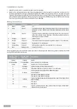
Page 8: ...e cylinder loses pressure indicating cylinder pressure discharge red alert indicator 4 Orange Input 3 Ignition input 5 Purple Output 2 Aux output operates opposite to ignition output 1 A continuous 6 Green Output 3 Fault alarm 1 A continuous 7 Yellow Blue Output 1 ETR ignition output for run solenoid 5 A continuous 8 Red Battery VE Power 8 to 35 V When upgrading from the old 7650 control unit refe...

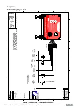
Page 9: ... 1 2 3 4 5 6 7 8 9 10 11 12 B A C D E F G H B A C D E F G H 1 2 3 4 5 6 7 8 9 10 11 12 A4 COPYRIGHT ALL RIGHTS RESERVED This drawing is the property of REMOTE CONTROL TECHNOLOGIES PTY LTD RCT and is not to be copied or used in whole or in part for any purpose without the express authority of RCT The drawing is to be returned to RCT on demand FIRE SYSTEM STATUS PANEL EXTERNAL WIRING www rct net au ...

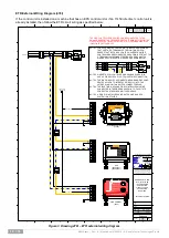
Page 10: ...L TECHNOLOGIES PTY LTD RCT and is not to be copied or used in whole or in part for any purpose without the express authority of RCT The drawing is to be returned to RCT on demand ENERGISED TO RUN ETR IDLE TIMER 11450 EPS FIRE CONTROLLER CIRCUIT TO SUIT CATERPILLAR MACHINES EXTERNAL WIRING www rct net au UNCONTROLLED DOCUMENT REV 1 DWG No 478i STATUS NTS SCALE Released SHEET 1 of 1 BY EY DRN CW DAT...

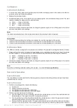
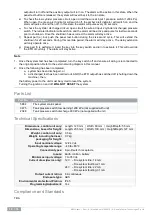
Page 11: ...bration mode for more than 10 seconds and then release it You should now be in NO EXTEND mode denoted by the flashing alert indicator a Green Flashing 6 seconds no extend b Amber Flashing 15 seconds no extend c Red Flashing 20 seconds no extend 2 Activate and release the panel test button to change the periods required Turn off the power to the control unit when complete to save settings Note Sele...

Page 12: ...ve Note 1 Once the system test has been completed turn the key switch off and ensure all wiring is reconnected to the original position Refer to the external wiring diagram in this manual 2 Once the following has been completed a system has been discharged or b a discharged test has been carried out AND the ETR output has switched off shutting down the machine then the battery power to the unit mu...

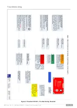
Page 13: ...M0030 docx Rev 1 8 Modified on 14 06 2019 Remote Control Technologies Pty Ltd 13 16 Troubleshooting Figure 4 Flowchart FC0025 Troubleshooting flowchart ...

Page 14: ...ogrammable Logic Controller ETS Energised To Stop POT Potentiometer ESD Engine Shutdown PPM Pulses Per Metre FET Field Effect Transistor PWM Pulse Width Modulation GND Ground PWR Power H Hours Rev Revision HEX Hexadecimal Numbering System RF Radio Frequency ID Identity RH Relative Humidity i e That is rpm Revolutions per minute In Input RX Receiver IP Ingress Protection RS232 Recommended Standard ...

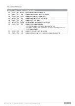
Page 15: ...tion 1 3 05 05 2014 DH Updated Installation Instructions section 1 4 06 01 2015 MT Updated Parts List section 1 5 25 09 2015 CamB Revised manual and updated to new format 1 6 12 10 2015 DH Updated terminology throughout Control unit replaced controller panel and fire unit Panel test button replaced test switch shutdown test delay extension and delay extension 1 7 19 06 2018 JB Updated Technical Sp...

Page 16: ...Discover more www rct global com sales rct global com AUSTRALIA 61 0 8 9353 6577 AFRICA 27 0 83 292 4246 CANADA 1 705 590 4001 RUSSIA CIS 7 910 411 11 74 SOUTH AMERICA 56 9 3417 0004 USA 1 801 938 9214 ...

Reviews: