11
E
Se
ri
es
P
ad
lo
ck
17
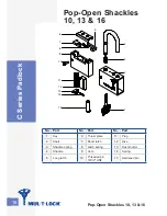
4
6
8
5
19
2
3
10
11
12
7
9
4
3
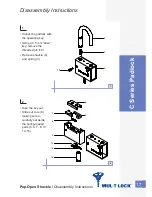
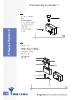
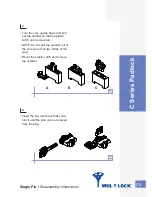
Remove bumper (17).
Using 2.5 mm “allen” key insert into hole (located beneath bumper)
and loosen screw (19) until until the cylinder cover can be removed (Do
not disassemble completely).
Remove cylinder front cover (2), shutter spring (4) and shutter (5).
Take out cylinder (6) and activator cam (8).
•
•
•
•
4
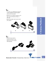
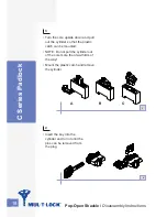
NOTE: It is not needed to
disassemble the locking
mechanism for re-keying!
Assembly tip
Check that the
mechanism works
properly before inserting
the bolt!
•
•
Sliding Bolt (SBE) /
Disassembly Instructions
Summary of Contents for G Series
Page 1: ...Padlock Service Manual ...
Page 2: ......
Page 44: ...NOTES ...
Page 45: ......
Page 46: ......
Page 47: ......


