6
E
Se
ri
es
P
ad
lo
ck
3-A
Assembly Instructions
1
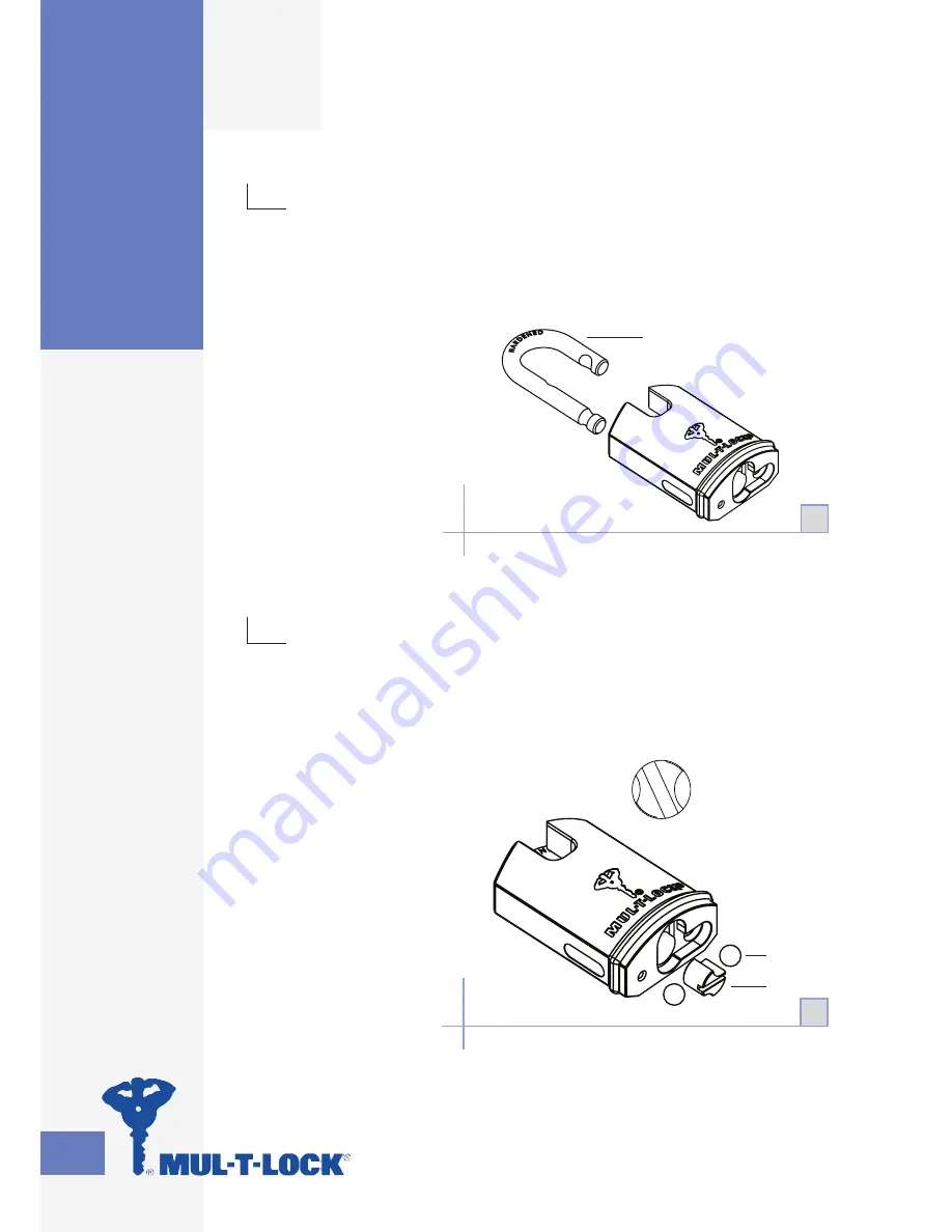
Insert shackle (2) in the position as illustrated.
NOTE: Pay special attention to shackle
position (height and rotation)!
•
•
2
Insert two ball bearings (9).
Insert activator cam (3) in shown position.
NOTE: Activator cam (3) is not symmetrical.
See diagram 3-A.
•
•
•
Protected shackle /
Assembly Instructions
9
3
2
Smaller
groove
toward the
longer leg of
the shackle
1
2
Summary of Contents for G Series
Page 1: ...Padlock Service Manual ...
Page 2: ......
Page 44: ...NOTES ...
Page 45: ......
Page 46: ......
Page 47: ......


