– 95 –
KC5™ Key Cutting Machine
User Manual
Introduction
Safety Notices
System
Specifications
Functional
Description
Operator Manual
Maintenance
Appendixes
Introduction
System
Specifications
Safety Notices
Functional
Description
Packing and
Transportation
Operator Manual
Maintenance
Appendixes
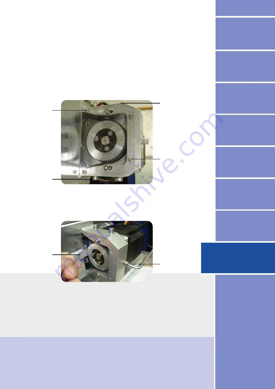
Release 4 cover screws and remove transparent cover.
Release (do not remove) 4 motor fixing screws located around belt
housing, to allow the movement of the motor.
Use spacer (provided) to adjust required gap between belt pulley and
motor housing. Attache spacer to motor housing and rotate tensing
screw until belt pulley is touching the spacer.
Cover screw
Motor screw
Cover screw
Motor screw
Spacer
Tensing Screw
Summary of Contents for KC5
Page 1: ...Computerized Key Cutting Machine KC5TM USER OPERATION MANUAL ...
Page 13: ... 12 3 2 Machine Layout and Measurements System Specifications D 340 W 525 Top view ...
Page 33: ... 32 Functional Description 5 2 General Machine View ...
Page 35: ... 34 Functional Description General rear view ...
Page 39: ... 38 Functional Description Z axis sensor Z axis Probe Z axis sensor ...
Page 43: ... 42 Tool replacement Functional Description Cutter 2 Cutter 3 Cutter 1 Tool pictures ...
Page 99: ...NOTES ...


