49
G
S
er
ie
s
Pa
dl
oc
k
Service Instructions
These assembly instructions are intended to walk you through the assembly process,
starting with the padlock disassembled. If you start dismantling an assembled lock,
please refer to the next page for instructions on removing the security pin.
•
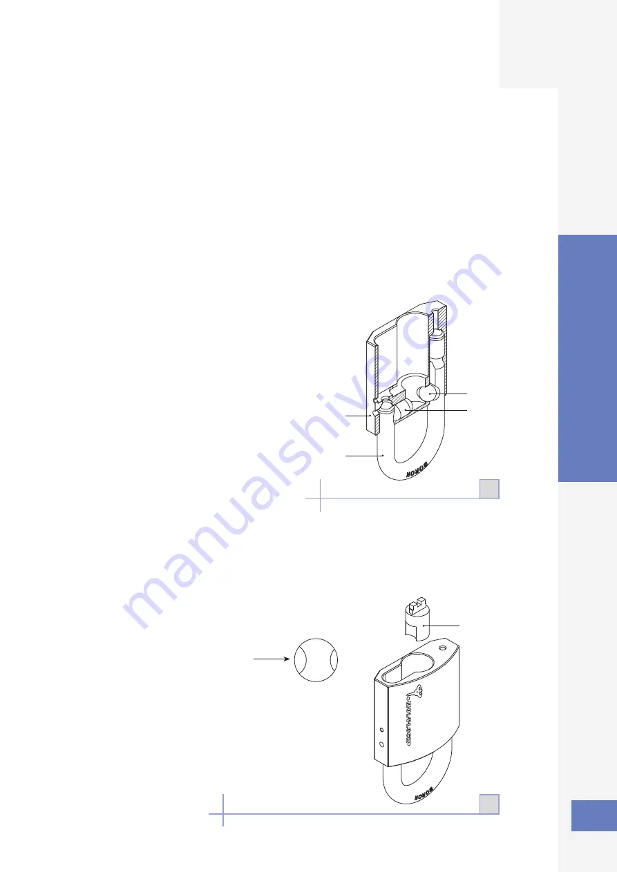
Insert the shackle (8) into lock body, hold the padlock body (5) upside down.
•
Push the two elongated ball bearings (part 4 for G-55 padlocks; parts 4 & 9 for G-47
padlocks) through the cylinder opening, one per side.
Note:
For G-47, ensure that the elongated ball bearing (4) is placed in the direction of the
short leg of the shackle (8).
• Insert the cam activator (3) via the cylinder opening.
Note:
For G-47 models make sure that the deepest groove is facing the short leg of the
shackle (2A).
2A
2
1
5
8
4
9
3
Assembly
Summary of Contents for NE10L
Page 1: ...Service Manual Padlocks ...


