background image


Installation 

Connecting sensors to the terminal 


12 

V7.20210115 

30322507-02-EN 


  You have connected the terminal to the ISOBUS. 


Connecting sensors to the terminal 

The terminal can receive signals from the following sensors: 
 

  Work position sensor 

Purpose: 


  Display of the work position on the start screen. 


  Transmission of the signal received through the signal socket to the ISOBUS. 

Possible signal sources: 


  7-pin signal socket on the sensor connection of the terminal. 


  An ISOBUS job computer. 


  Speed sensor 

Purpose: 


  Display of the speed on the start screen. 


  Transmission of the signal received through the signal socket to the ISOBUS. 

Possible signal sources: 


  7-pin signal socket on the sensor connection of the terminal. 

4.3 

Summary of Contents for SMART570

Page 1: ...ions SMART570 Version V7 20210115 30322507 02 EN Read and follow these instructions Keep these instructions in a safe place for later reference Please note that there might be a more recent version of...

Page 2: ...07 02 EN As of software version 0 3 2 0 Original instructions Original language German M ller Elektronik GmbH Franz Kleine Stra e 18 33154 Salzkotten Germany Phone 49 0 5258 9834 0 Fax 49 0 5258 9834...

Page 3: ...g the terminal in the vehicle cab 11 4 2 Connecting the terminal to the ISOBUS 11 4 3 Connecting sensors to the terminal 12 5 Basic control principles 13 5 1 Initial start up 13 5 2 Operating the term...

Page 4: ...ic of connected devices 25 6 5 2 Deleting the object pool 26 6 6 Information 27 7 Technical specifications 28 7 1 Technical specifications of the terminal 28 7 2 Pin assignment 29 7 2 1 9 pin CPC conn...

Page 5: ...sing If the casing is opened its imperviousness can be changed Read the operating instructions to the agricultural device which you want to control by using the product Intended use The terminal is us...

Page 6: ...that need to be performed in several steps If there is a risk involved in carrying out any of these steps a safety warning appears in the instructions themselves Safety instructions always directly p...

Page 7: ...ns with the product We use the following symbols throughout these Operating Instructions to identify different operating instructions Type of depiction Meaning 1 2 Actions that must be performed in su...

Page 8: ...can be operated both via the membrane keyboard and via touch display The latter supports the driver with text input by providing a complete keyboard on the screen The rotary encoder enables rapid val...

Page 9: ...ews Speaker Connection to the 7 pin signal socket Connection to ISOBUS Pressure compensation membrane must never be covered Rating plates Abbreviations on the rating plate Abbreviation Meaning HW Hard...

Page 10: ...legal provisions of the EU When it has reached the end of its service life please dispose of this product as electronic scrap in accordance with all applicable waste management laws EU declaration of...

Page 11: ...sert the long bolt through the assembled bracket 5 Screw in the long bolt until the terminal is firmly attached You can now attach the terminal with the bracket on a round pipe e g on the ME mounting...

Page 12: ...ay of the work position on the start screen Transmission of the signal received through the signal socket to the ISOBUS Possible signal sources 7 pin signal socket on the sensor connection of the term...

Page 13: ...l be requested to confirm the button assignment 16 The following screen appears You can change the system settings through this screen 2 Configure the system settings 18 3 Configure the speed sensor 2...

Page 14: ...ton Sends a cancel signal to the job computer Cancels the input of a value The input box is exited and the previous valid value is restored Acknowledges alarms Enter button Opens an input box Confirms...

Page 15: ...nt to change 3 Change the value 4 Confirm the input Changing parameters with the rotary encoder 1 Call up a screen with adjustable parameters For example 2 Select the parameter that you want to change...

Page 16: ...every time the terminal is started You have started the terminal 1 The button assignment will be loaded 2 The following message appears Confirm or discard the AUX button assignments in the following...

Page 17: ...een appears 2 Configure the desired parameters App selection On this screen you can switch between different apps for example between the terminal and a connected job computer or joystick On the start...

Page 18: ...evious page of the screen Scrolls to the next page of the screen The following parameters can be configured on this screen Parameter Meaning Date Current date Time Current time Time zone Current time...

Page 19: ...ge different format and unit settings for the terminal On the start screen press The following function icons appear on the screen Function icon Meaning Switches back to the previous screen Changes th...

Page 20: ...minals on the ISOBUS each terminal can be assigned with an instance number The instance number serves to assign job computers to terminals Number of navigation buttons With 1 the terminal uses button...

Page 21: ...he terminal The start screen displays the icon CAN Bus A work position signal is received through the CAN bus No selection A work position signal was not selected Working width in m Current working wi...

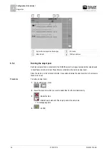
Page 22: ...e calibration 6 Drive straight ahead over the marked distance 7 Stop after 100 m 8 Terminate the calibration The number of impulses appears on the Counted impulses line 9 Save the result You have cali...

Page 23: ...t of counters Date of the last counter reset Button assignment for AUX operating devices The terminal offers you the possibility of assigning the functions of an ISOBUS job computer to the buttons of...

Page 24: ...signed to a button select the joystick to which you want to assign the function for example 6 Press on the current button assignment for example If there is no button assignment yet for the function p...

Page 25: ...ne or more object pools Speed impulses Currently measured speed impulses per minute Work position sensor Current impulses that are being transmitted by the work position sensor Diagnostic of connected...

Page 26: ...in its software onto the terminal These files are collectively referred to as object pool Since the memory on the terminal is limited it is sensible to delete the object pools for job computers that a...

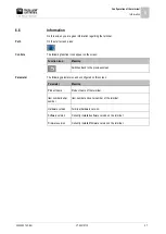
Page 27: ...ning Switches back to the previous screen The following parameters can be configured on this screen Parameter Meaning Product name Product name of the terminal Item number serial number Item number an...

Page 28: ...g without bracket Dimensions W x H x D 212 mm x 135 mm x 44 mm Ingress protection code IP6K6 in accordance with ISO 20653 EMC In accordance with ISO 14982 ESD protection In accordance with ISO 10605 C...

Page 29: ...ly 12 V 2 CAN_L_In CAN Input 3 CAN_L_Out CAN Output 4 CAN_H_In CAN Input 5 CAN_H_Out CAN Output 6 TBC_PWR Ignition Input 7 ECU_PWR Supply 12 V 8 Not connected 9 ECU_GND Ground 5 pin M12 connector Pin...

Page 30: ...e PC 2 Press these buttons simultaneously and hold to start the download mode 3 Press and hold this button until the logo appears on the screen 4 In Downloadmanager 2 select the terminal 5 Mark the te...

Reviews: